Wiring Instructions
1. Overview
The examples in this course use a consistent wiring diagram and hardware resource configuration, so all wiring instructions are collected in this article.
Note: You do not need to connect every wire at the same time. Connect only the wiring required by the example you are running.
2. Firmware Download
2.1 Wiring Between STM32 and STLinkV2
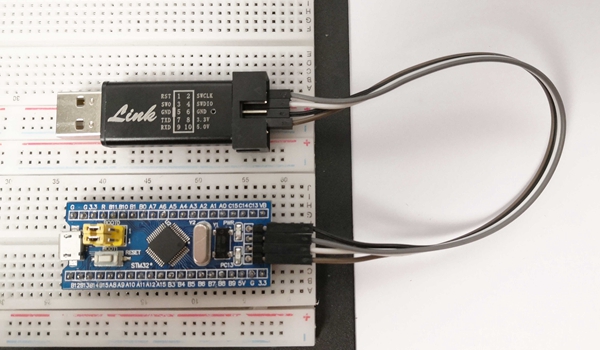
Use STLinkV2 to download firmware to STM32.
Wiring diagram between STM32 and STLinkV2
| STM32 | STLinkV2 |
|---|---|
| SWIO / IO | SWDIO |
| SWCLK / CLK | SWCLK |
| GND | GND |
| 3V3 | 3.3v |
3. Serial Port UART
3.1 Serial Port Resources
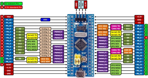
STM32F103 provides three serial port resources: UART1, UART2, and UART3. In the STM32 version of the servo gimbal course, the three serial port ports are assigned as follows:
UART1connects to the Bus Servo adapter board to control the Bus ServoUART2connects to the USB to TTL module for log outputUART3connects to OpenMV to receive information from image processing
3.2 Wiring Between STM32 and the Bus Servo
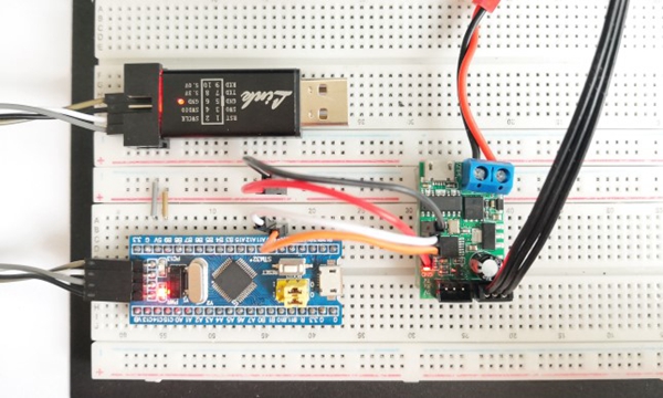
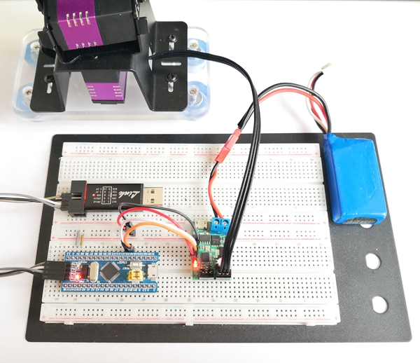
serial port 1 is connected to the TTL interface of the bus servo adapter board to control the bus servo.
Wiring diagram between STM32 and the bus servo adapter board
| STM32F103 GPIO | Bus Servo Adapter Board |
|---|---|
| PA_9 (UART1 Tx) | Rx |
| PA_10 (UART1 Rx) | Tx |
| 5v | 5v |
| GND | GND |
3.3 STM32 and USB to TTL Module
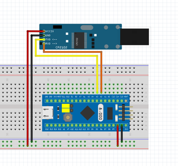
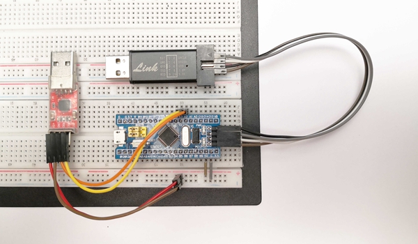
STM32 serial port 2 is connected to the USB to TTL module to send log information to the PC.
Wiring diagram between STM32 and USB to TTL
| STM32F103 GPIO | USB to TTL Module |
|---|---|
| PA_2 (UART2 Tx) | Rx |
| PA_3 (UART2 Rx) | Tx |
| GND | GND |
Connect the USB port of the USB to TTL module to the computer USB port.
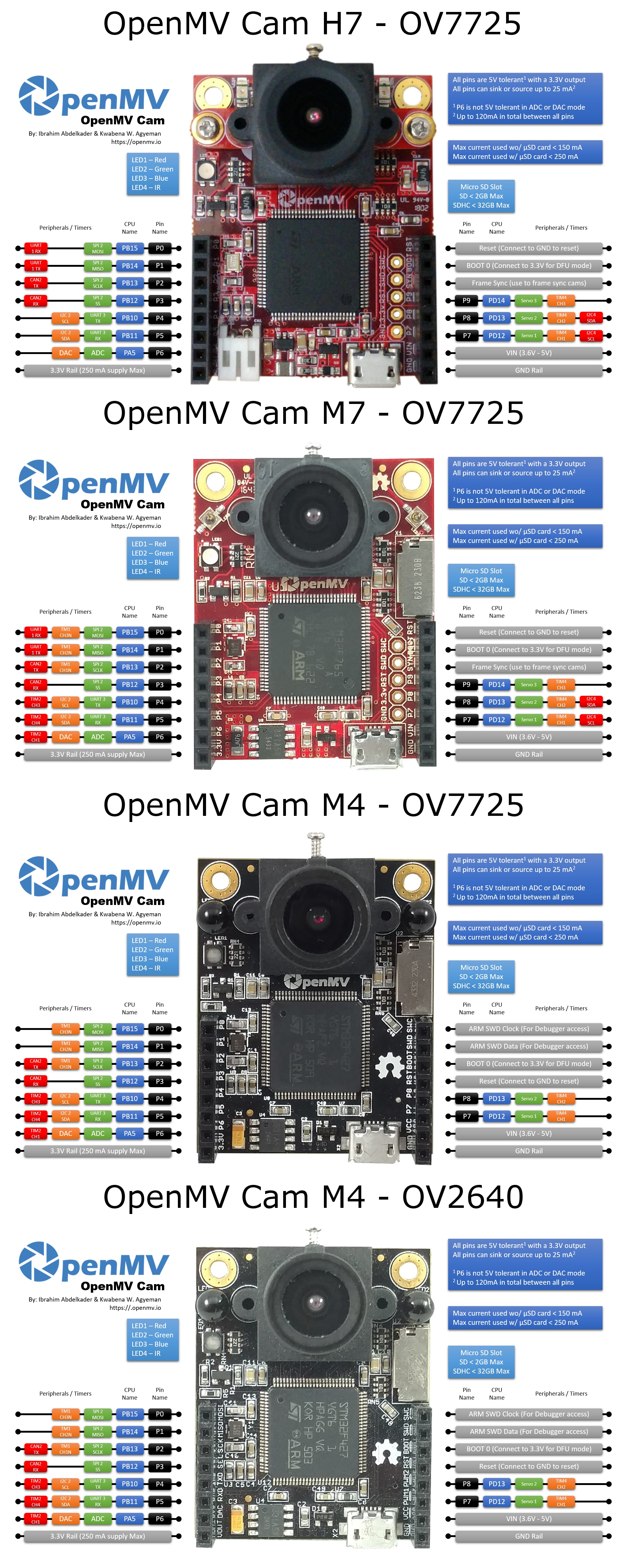
3.4 Wiring Between STM32 and OpenMV
STM32 serial port 3 connects to OpenMV to receive information from image processing.
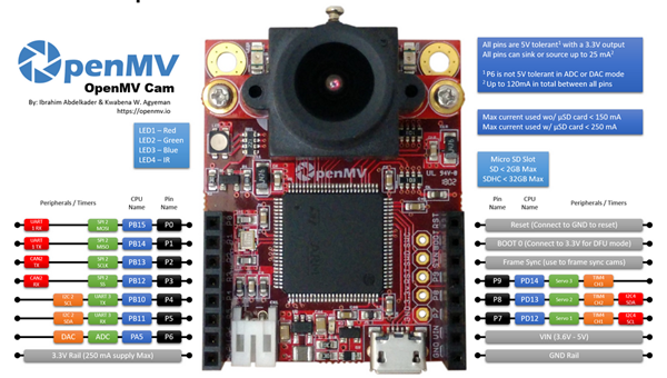
OpenMV Pinout - High-Resolution Image
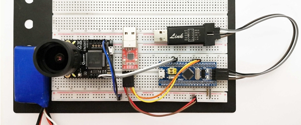
3.4.1 OpenMV3
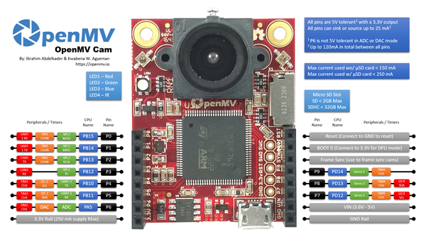
| STM32F103 | OpenMV3 |
|---|---|
| PB_11 (UART3 Rx) | P4 (PB10, UART3 Tx) |
| PB_10 (UART3 Tx) | P5 (PB11, UART3 Rx) |
| GND | GND |
| 5V | VIN |
Note: Do not connect the STM32F103 5V pin to the OpenMV 3.3v pin. Doing so will damage the OpenMV.
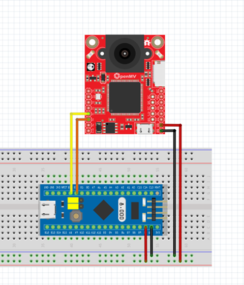
3.4.2 OpenMV4
OpenMV3 and OpenMV4 have the same layout. The UART3 pins and positions are compatible.
| STM32F103 | OpenMV3 |
|---|---|
| PB_11 (UART3 Rx) | P4 (PB10, UART3 Tx) |
| PB_10 (UART3 Tx) | P5 (PB11, UART3 Rx) |
| GND | GND |
| 5V | VIN |
Note: Do not connect the STM32F103 5V pin to the OpenMV 3.3v pin. Doing so will damage the OpenMV.
4. Other Sensors
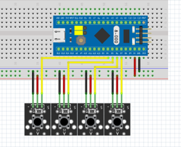
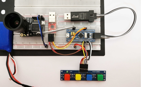
4.1 Wiring Between STM32 and the Button Module
Some examples use button interaction. Four buttons are required to increase and decrease the yaw and pitch angles.
For easier wiring, this example uses a four-button independent module. You can also use four separate button modules or build the circuit on a breadboard.
| STM32F103 | Button Module | Notes |
|---|---|---|
| PB_4 | KEY1 | Yaw angle increase + button |
| PB_5 | KEY2 | Yaw angle decrease - button |
| PB_6 | KEY3 | Pitch angle increase + button |
| PB_7 | KEY4 | Pitch angle decrease - button |
| 5V | VCC | |
| GND | GND |
4.2 Laser Module
The laser spot experiment uses a laser pointer.
The laser pointer used for testing has a power of 5 mW and a wavelength of 650 nm. It can be driven directly by an IO pin. The simplest wiring method is to connect the positive terminal to STM32 5v and the negative terminal to GND.