Bus Servo Wiring and Power Solutions
Based on typical customer use cases, the wiring and power solutions in this guide can be grouped into the following three application scenarios according to the number of installed servo units:
- Standard Applications (1-6 servos)
- Complex Applications (7-14 servos)
- Large-Scale Applications (15 servos and above)
Standard Applications (1-6 servos)
- Suitable for standard single-system applications using 1-6 servo units under light-load operating conditions.
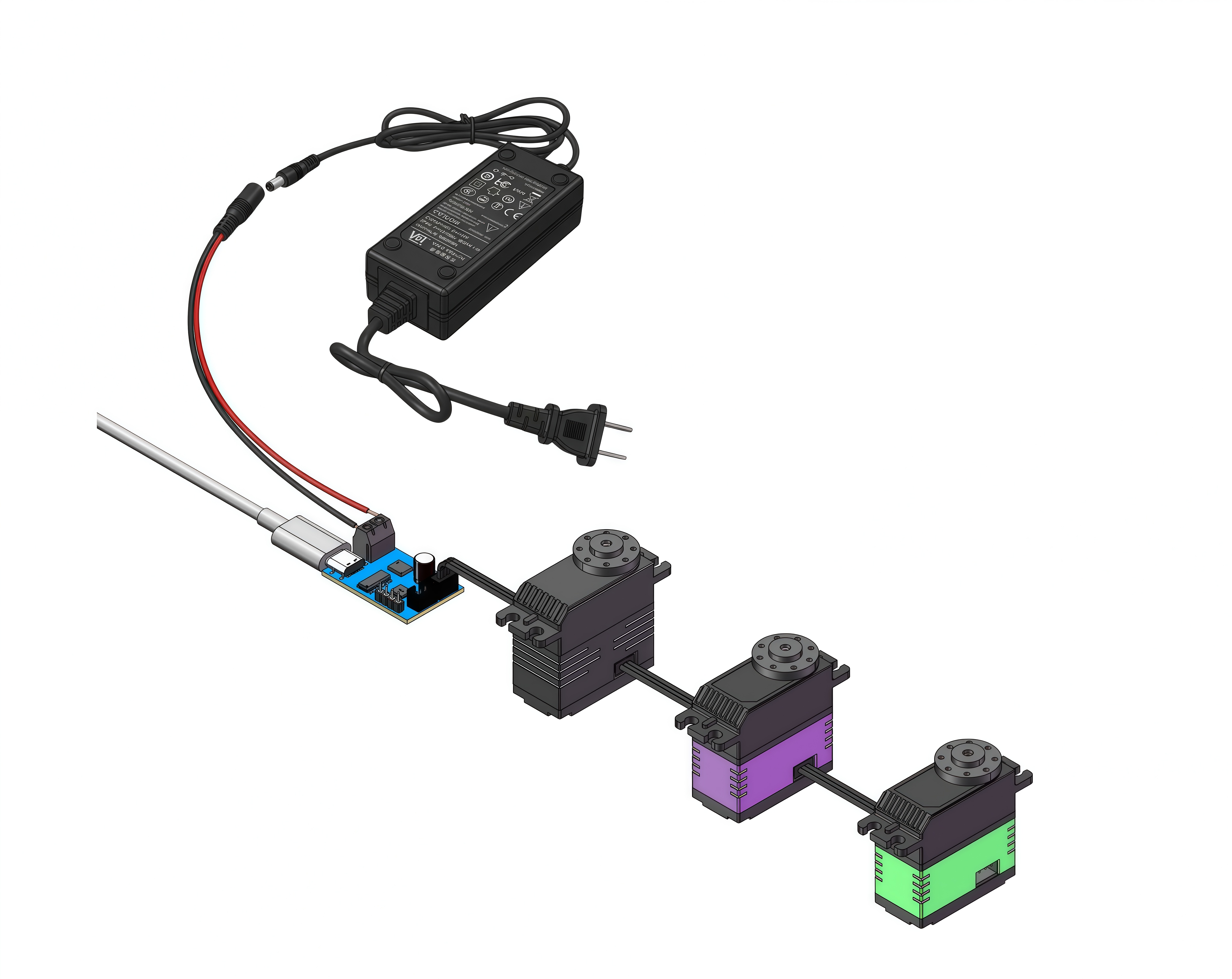
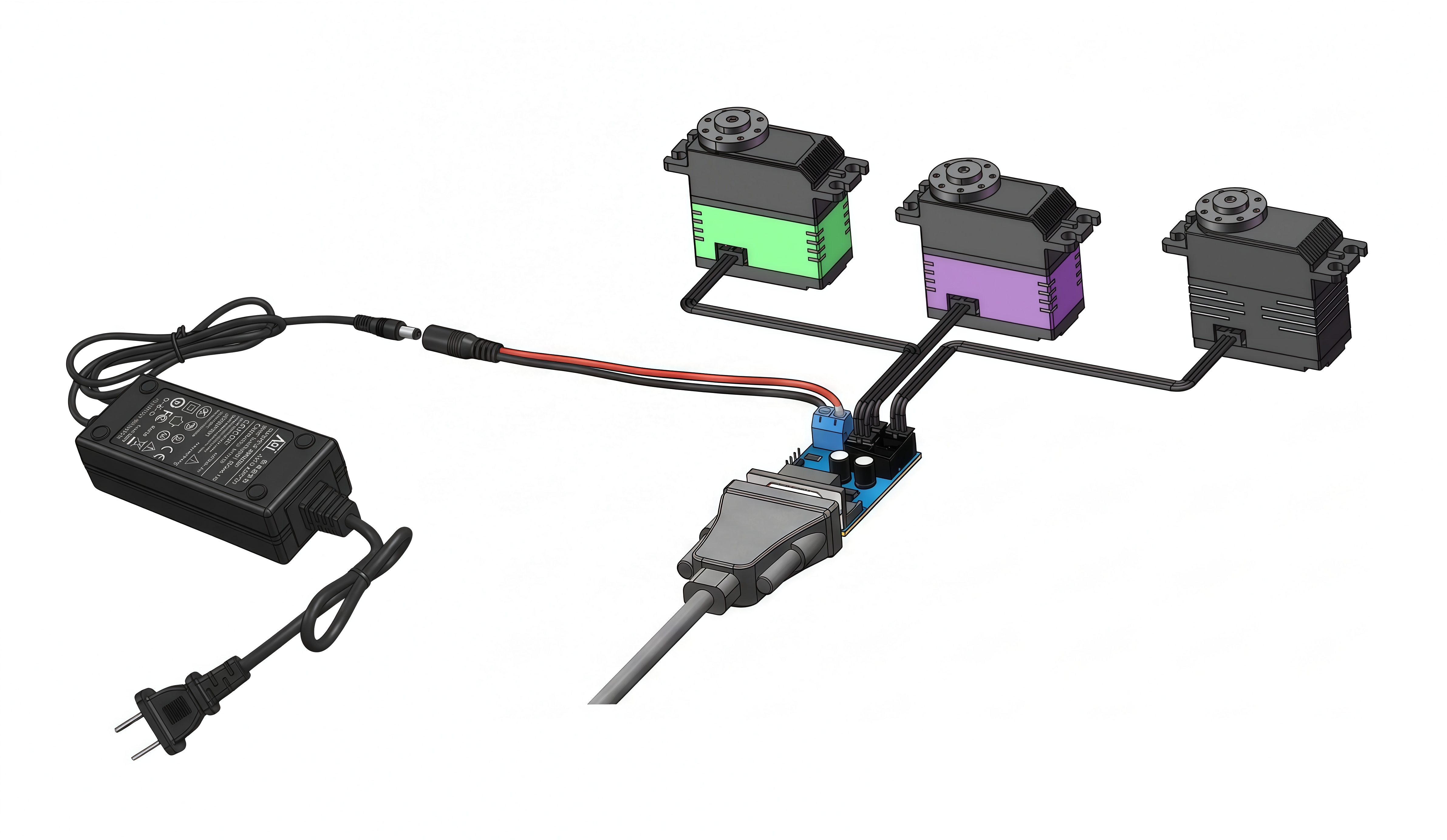
- Provided that the adapter board load capacity, wiring voltage drop, and connector loss are within acceptable limits, you may flexibly choose daisy-chain, parallel wiring, or combined daisy-chain and parallel connection wiring.
- For heavy-load conditions, such as applications using 100 kg-class high-torque servo units, reduce the number of connected units according to the actual total operating current.
Caution
The total operating current through a single UC-01 adapter board must not exceed 20 A.
Daisy-Chain
Parallel
Complex Applications (7-14 servos)
- Suitable for single-system applications using 7-14 servo units.
- As the number of servo units increases, pay close attention to the power demand of each servo, voltage drop over long wiring runs, and the current-carrying capability of the data cables.
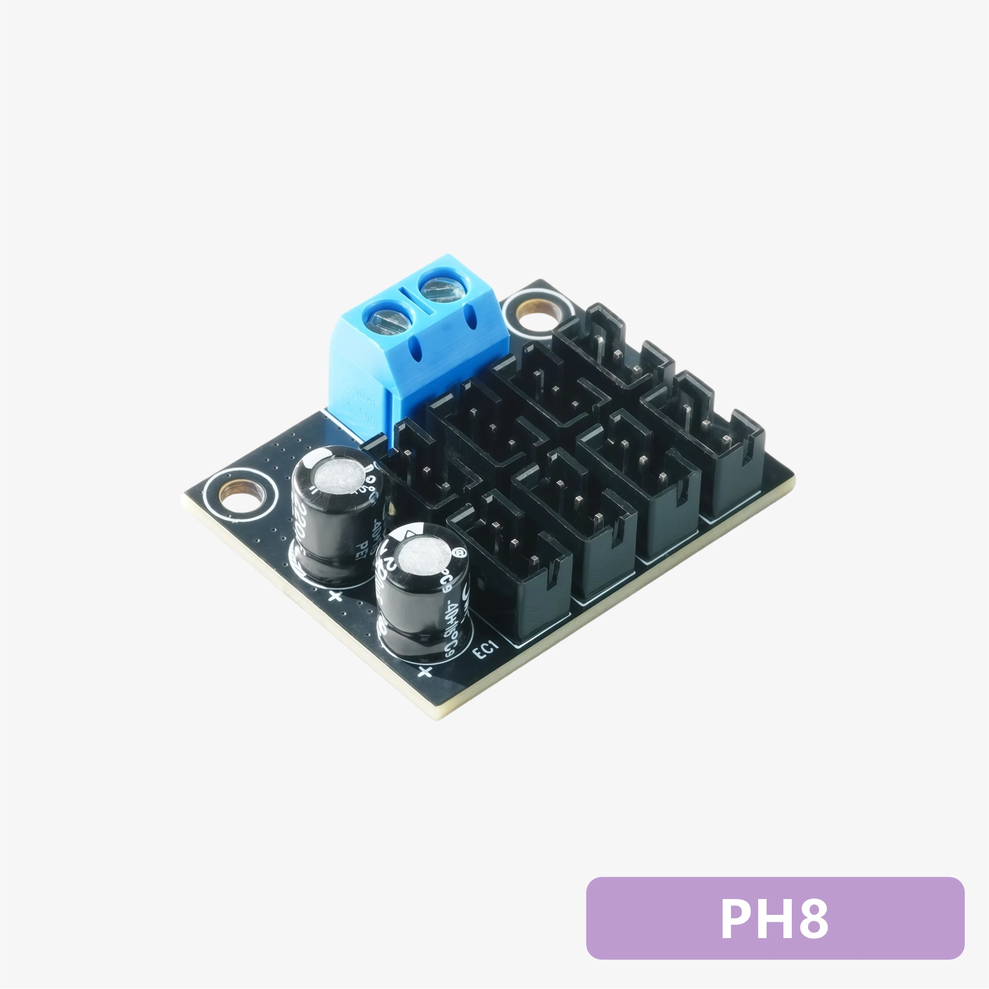
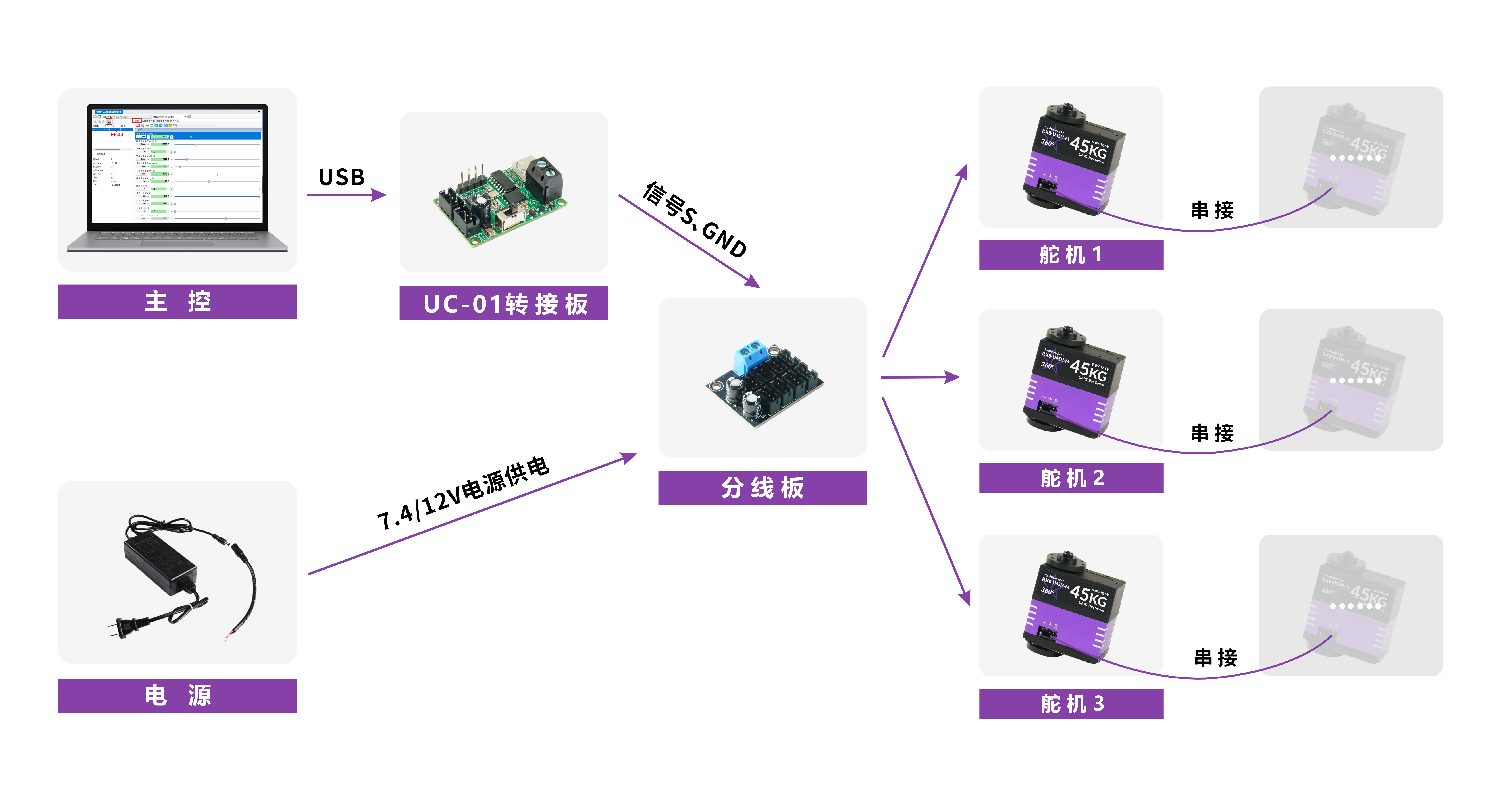
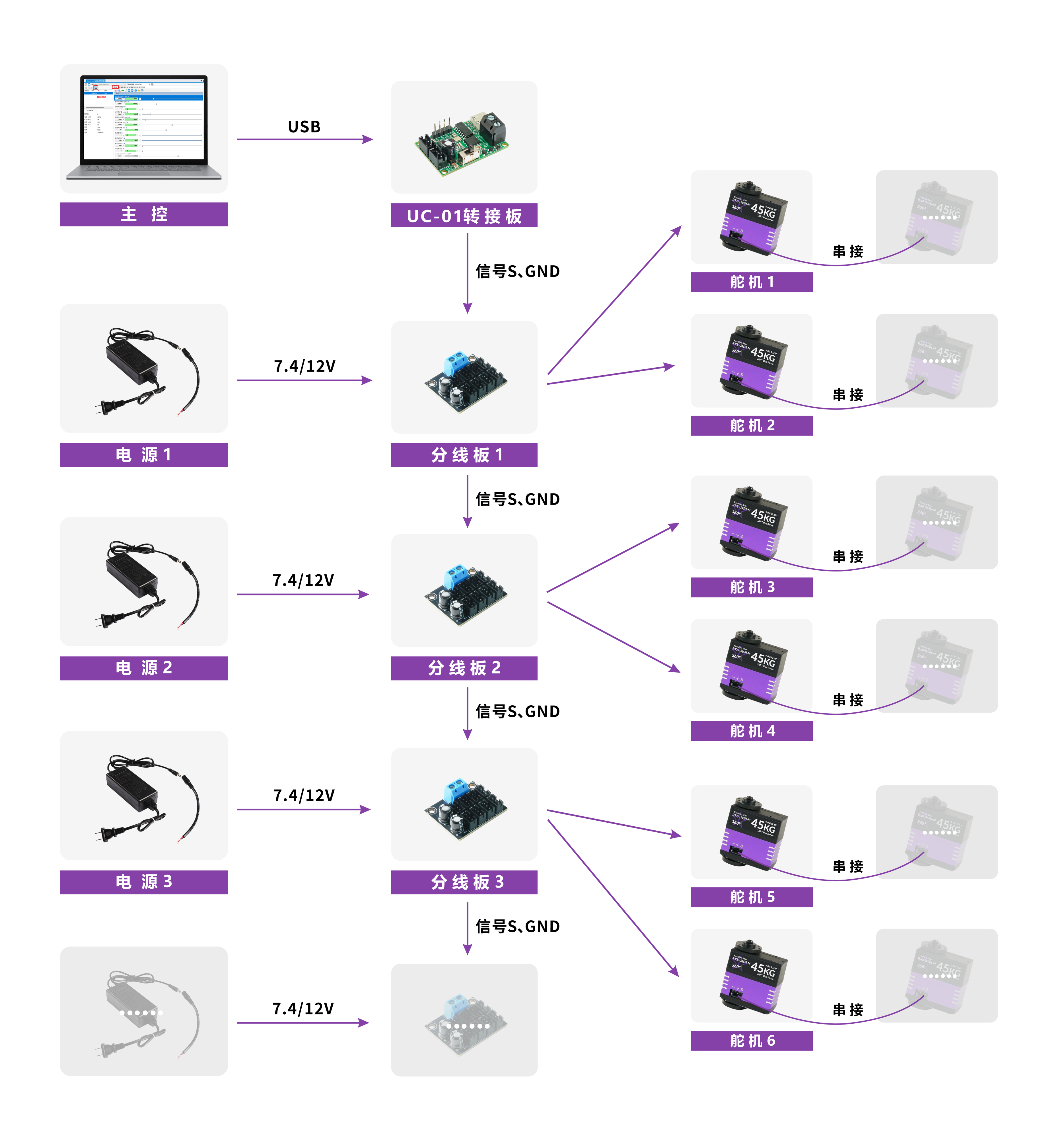
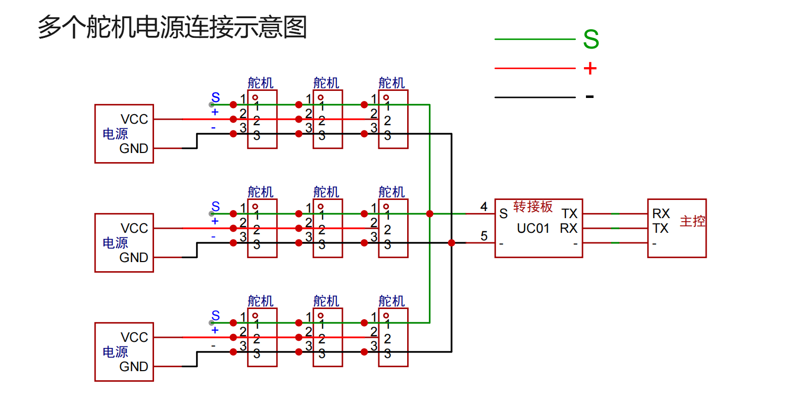
- Use a distribution board for power branching, and power the distribution board from an independent main supply loop to reduce line loss and improve power stability.
- You may use the matching distribution board directly, or design a compatible distribution board circuit according to project requirements.
- The number of servo units mounted in daisy-chain within a single branch is recommended not to exceed 6. Reduce this number accordingly for high-torque loads.
Recommended Wiring Scheme
Large-Scale Applications (15 servos and above)
- Suitable for large-scale single-system applications using 15 or more servo units.
- At this scale, use multiple distribution board units for grouped power supply and signal distribution to avoid excessive load on a single path.
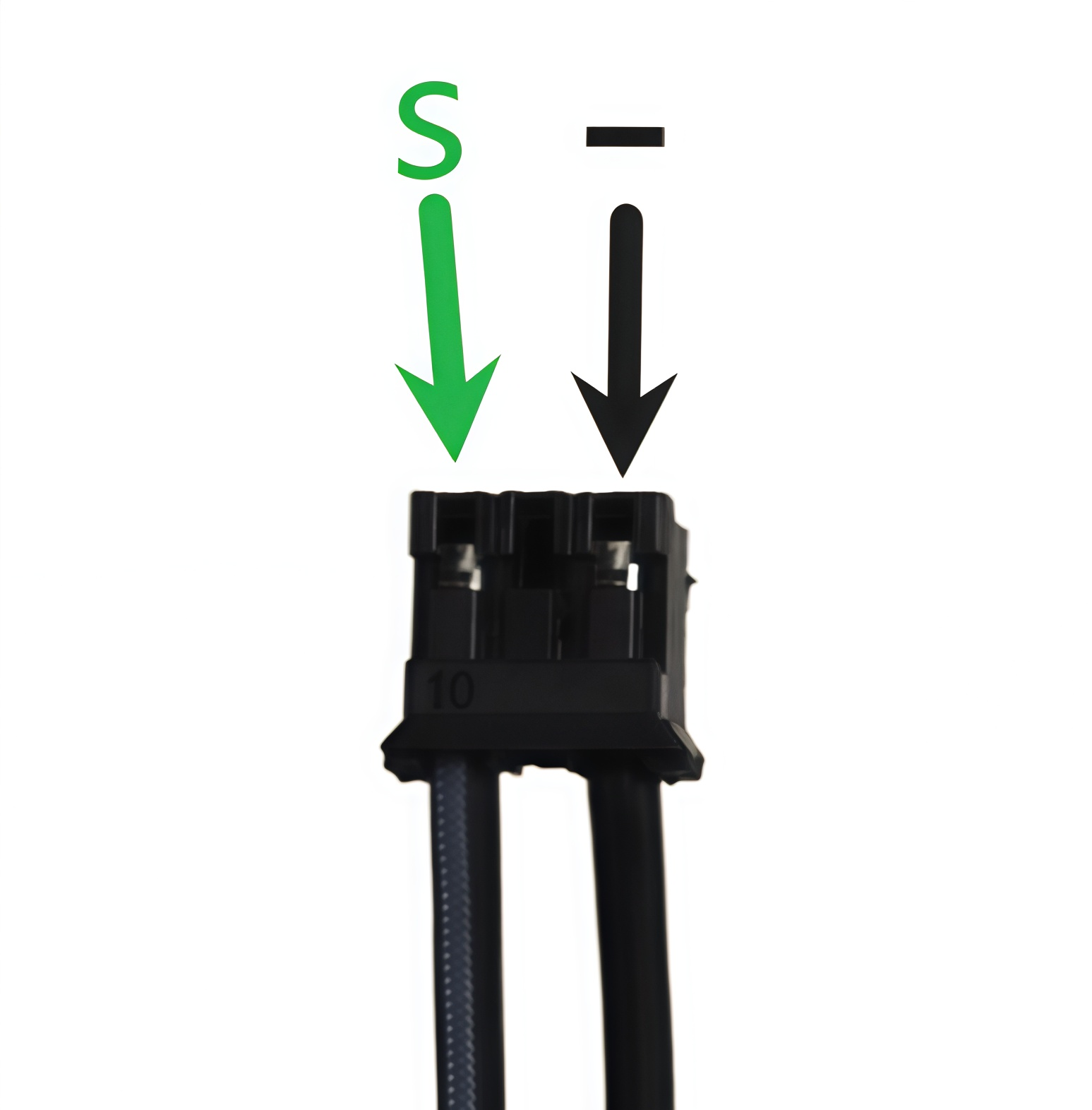
- Between distribution board units, and between each distribution board and the UC-01 adapter board, only the signal wire (S) and power negative wire (-, GND) need to be connected.
- After the adapter board is connected to the main controller and communication is established, unified control of all servo units on the bus can be achieved.
- For detailed wiring, refer to the diagrams and video demonstration below.
Wiring Diagrams
Data Cable Modification Instructions
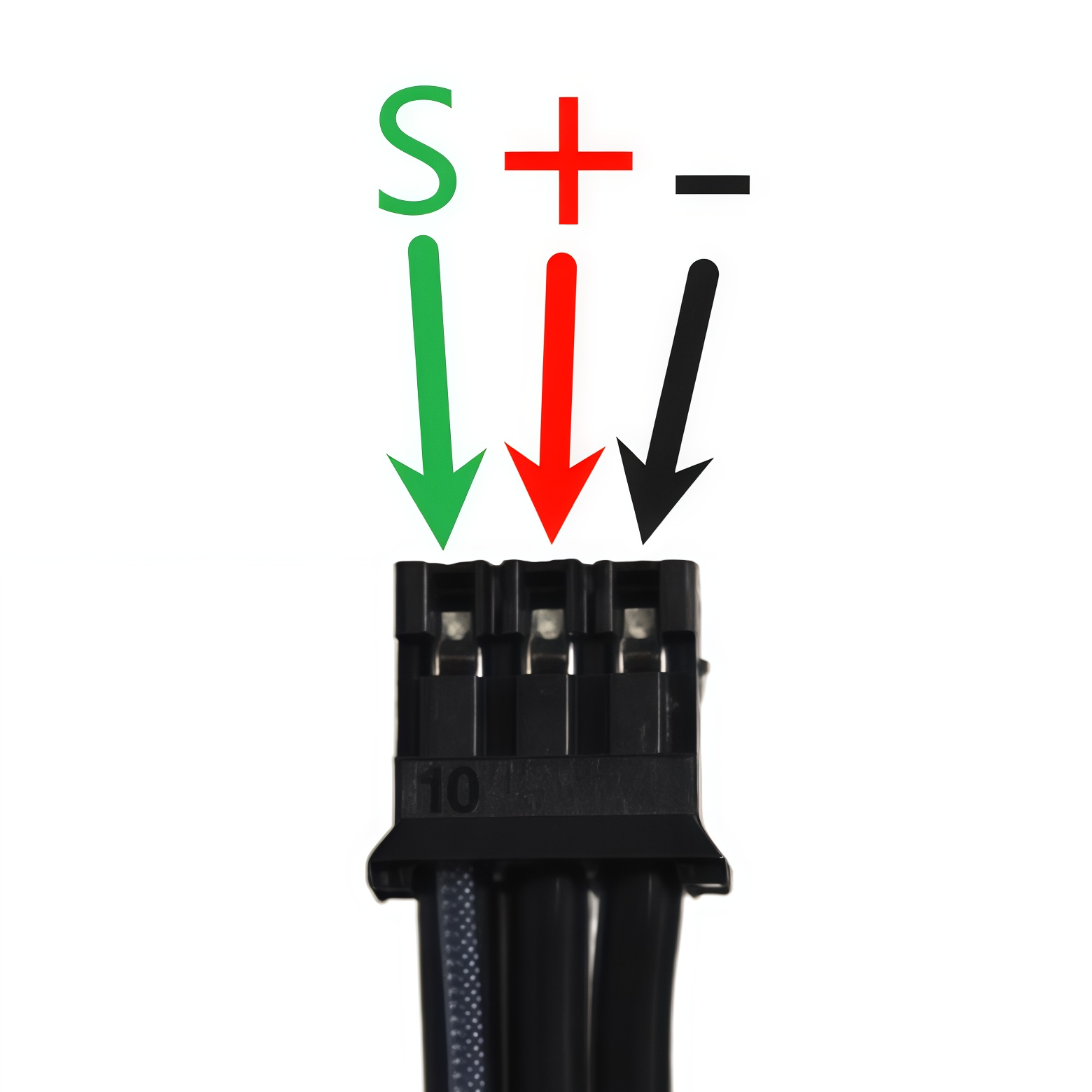
The supplied data cable can be modified as shown below, and then used for connections between distribution board units, and between a distribution board and the UC-01 adapter board.
| Before Modification | After Modification |
|---|---|
|
|
Wiring Video Demonstration
- If the video cannot load, watch it on YouTube.
Notes and Warnings
Warning
- The maximum length of the daisy-chain communication cable between two adjacent servo units is 1 m. If the cable length exceeds 1 m, use shielded cable to reduce the risk of signal interference and attenuation.
- Due to the inherent impedance of connectors and power cables, voltage drop and line loss may occur under high-current conditions. In actual designs, verification should be performed according to the specific application scenario, and the measured voltage under full operating conditions of the system should be used as the final criterion.