Wiring Methods for Various MCUs and the UC01 Servo Adapter Board
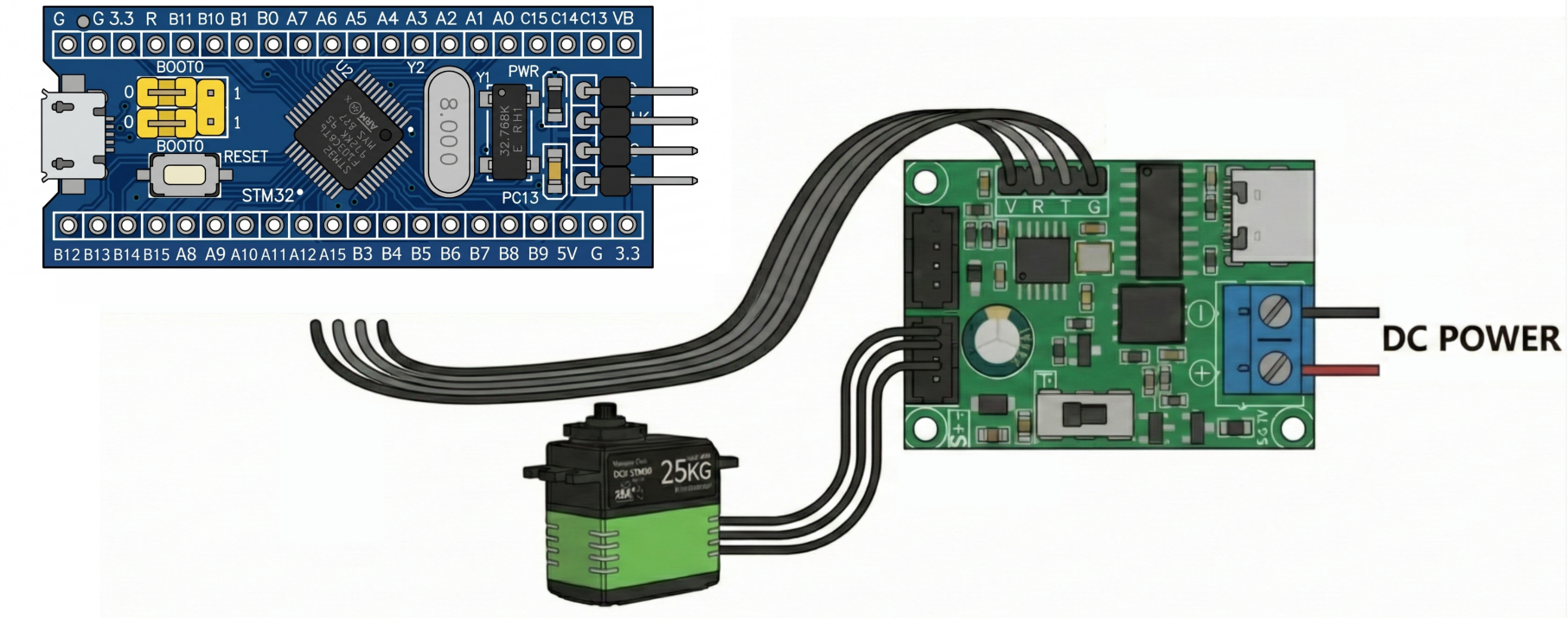
1. STM32F103 SDK
MCU Pin
UC01 Pin
Description
PA9 (UART1 TX)
RX
MCU transmit
PA10 (UART1 RX)
TX
MCU receive
5V
5V
5V power
GND
GND
Common ground
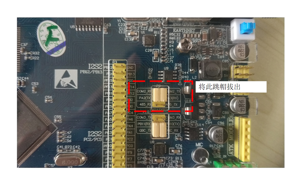
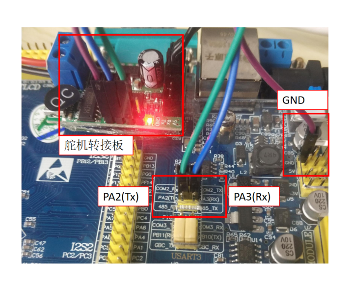
2. STM32F407 SDK
MCU Pin
UC01 Pin
Description
PA2 (USART2 TX)
RX
MCU transmit
PA3 (USART2 RX)
TX
MCU receive
GND
GND
Common ground
5V
5V
5V power (optional)
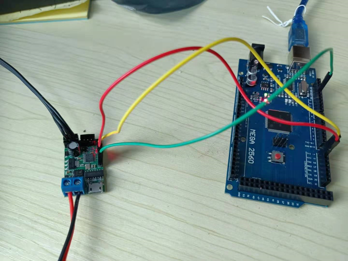
3. Arduino Mega2560
MCU Pin
UC01 Pin
Description
D15 (Serial3 RX)
TX
MCU receive
D14 (Serial3 TX)
RX
MCU transmit
GND
GND
Common ground
4. Arduino Uno
MCU Pin
UC01 Pin
Description
D0 (RX)
TX
MCU receive
D1 (TX)
RX
MCU transmit
GND
GND
Common ground
5V
5V
5V power
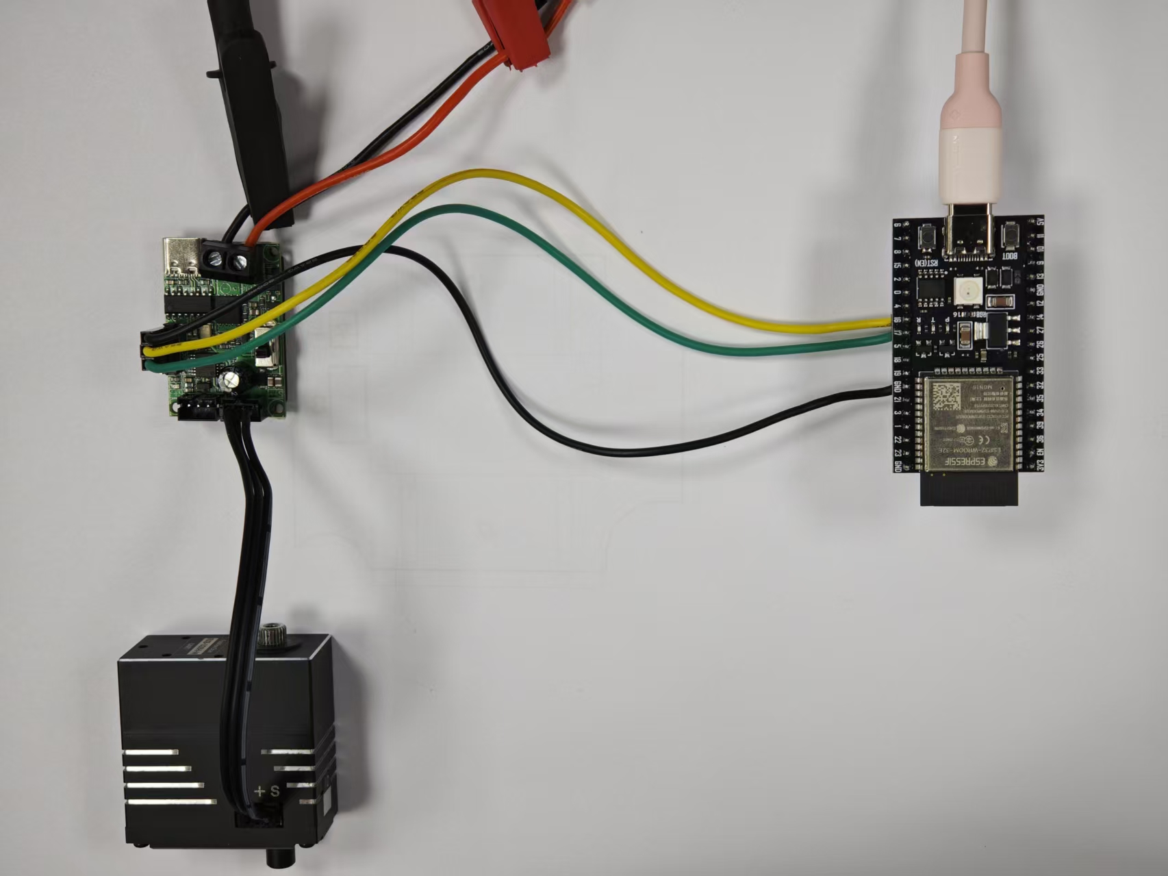
5. ESP32
MCU Pin
UC01 Pin
Description
GPIO16 (UART2 RX)
TX
MCU receive
GPIO17 (UART2 TX)
RX
MCU transmit
VIN / 5V
5V
5V power (optional)
GND
GND
Common ground
The ESP32 is powered through its Type-C port.
ESP32 Arduino extension package V2.0 and V3.0 differ in hardware serial port (UART) configuration. Some default pins and initialization methods have been updated.
If code written for V2.0 is run directly in a V3.0 environment, servo communication may become abnormal, unresponsive, or fail to control the device.
If you use V3.0, make sure to reconfirm the UART pin configuration and serial port initialization method.