Datasheet - CAN/USB Adapter and Configuration Board UC-06
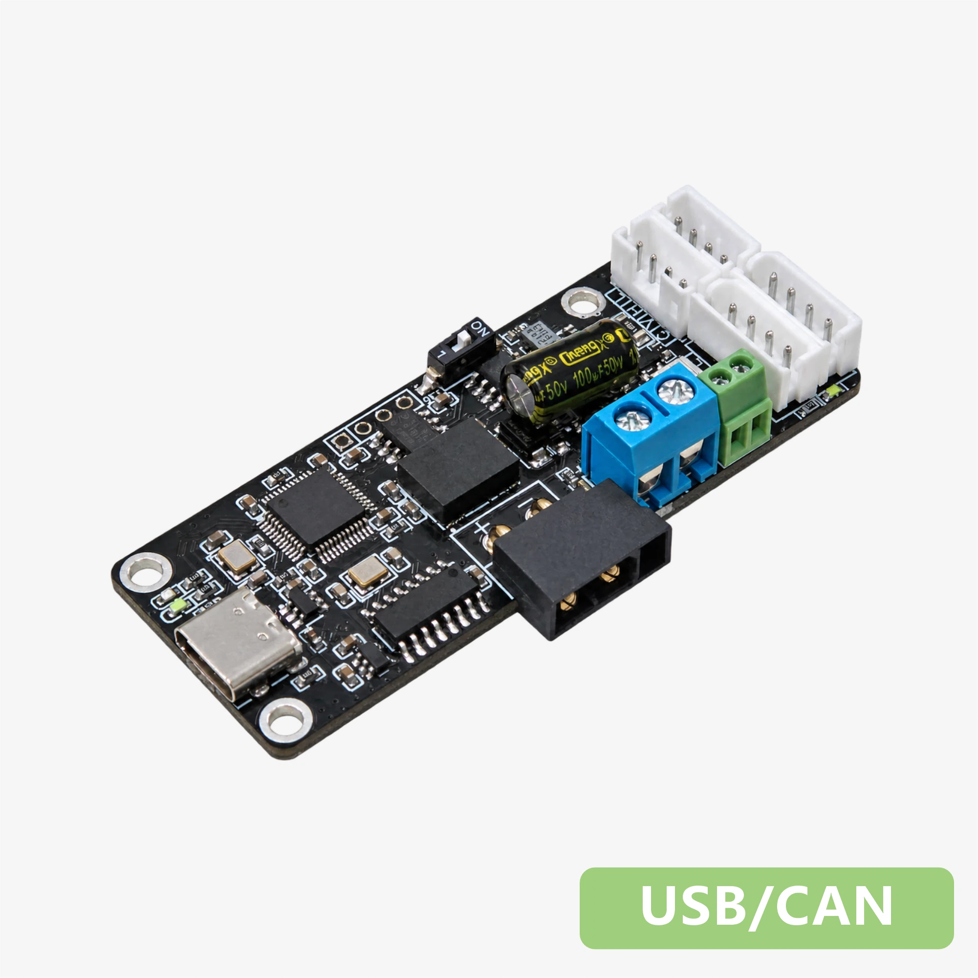
CAN/USB Adapter and Configuration Board UC-06
--
1. Features
- Communication speeds up to 1 Mbps
- Isolation voltage of 3 kV
- Type-C data interface with power and signal indicators
- Supports ID configuration, parameter settings, and communication between CAN bus servos and PCs or other platforms
- Multiple connection options with a 120 Ω termination switch
2. Specifications
| Parameter | Value |
|---|---|
| Input voltage | 8.0–25.2 V |
| Signal conversion | USB to CAN |
| Maximum communication speed | 1 Mbps |
| Isolation voltage | 3 kV |
| Maximum current capacity | 20 A |
| Serial port outputs | 1 |
| Data interface | Type-C |
| Operating temperature | -10 to 60 °C |
| Servo connectors | PH2.0 × 2, 5264-4P × 2 |
| Mounting holes | M3.0 × 3 |
| USB power / Servo power / Communication indicators | Red / Green / Blue |
| Dimensions | 70.1 × 26.6 mm |
| Weight | 14.3 g |
3. Interfaces and Pinout
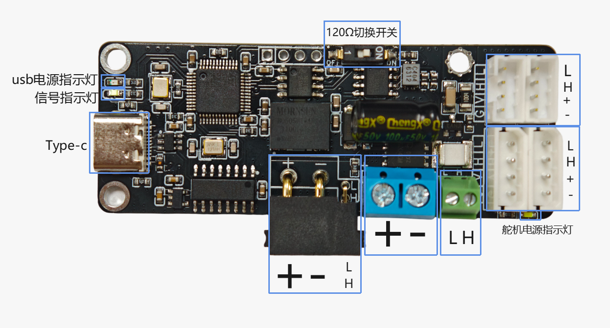
UC-06 Interfaces and Pinout
| Interface / Label | Description |
|---|---|
| Type-C | USB data interface for connecting to a PC |
| PH2.0 and 5264-4P servo connectors | Pins labeled L, H, +, and - correspond to CANL, CANH, power positive, and power negative; see the diagram above for their positions |
| XT30 (2+2) connector | Provides power positive, power negative, CANL, and CANH connections; see the diagram above for their positions |
| Power terminal block (+, -) | External power input: + is positive and - is negative |
| CAN terminal block (L, H) | L is CANL and H is CANH |
| 120 Ω termination switch | Switches the 120 Ω CAN bus termination resistor in or out |
| USB power indicator | Red |
| Servo power indicator | Green |
| Communication indicator | Blue; identified as the signal indicator in the diagram |