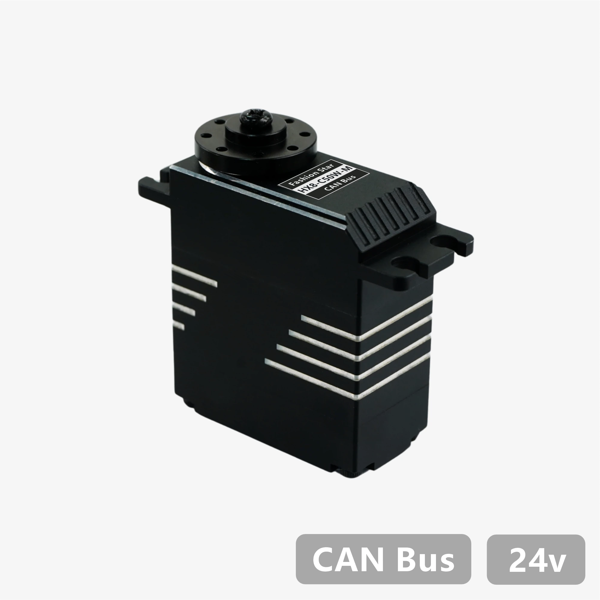
HX8-C50W-M・Datasheet
1. Features
- Designed with brushless motor / stainless-steel gear set / CNC All-Metal Housing
- CAN bidirectional communication, up to 1 Mbps, supports position and status feedback
- 12-bit absolute position encoder (4,096 counts resolution), supports arbitrary zero-point setting
- Supports a maximum multi-turn control range of ±368,640° (1,024 turns), with power-off position memory
- Built-in trapezoidal acceleration/deceleration for smooth motion control
- Provides three stop modes: torque holding / torque release / damping control
- Integrated protections for temperature, voltage, stall, power, and current, with intelligent power limiting
- Includes a visual Master / PC Software for configuration, supports firmware upgrade
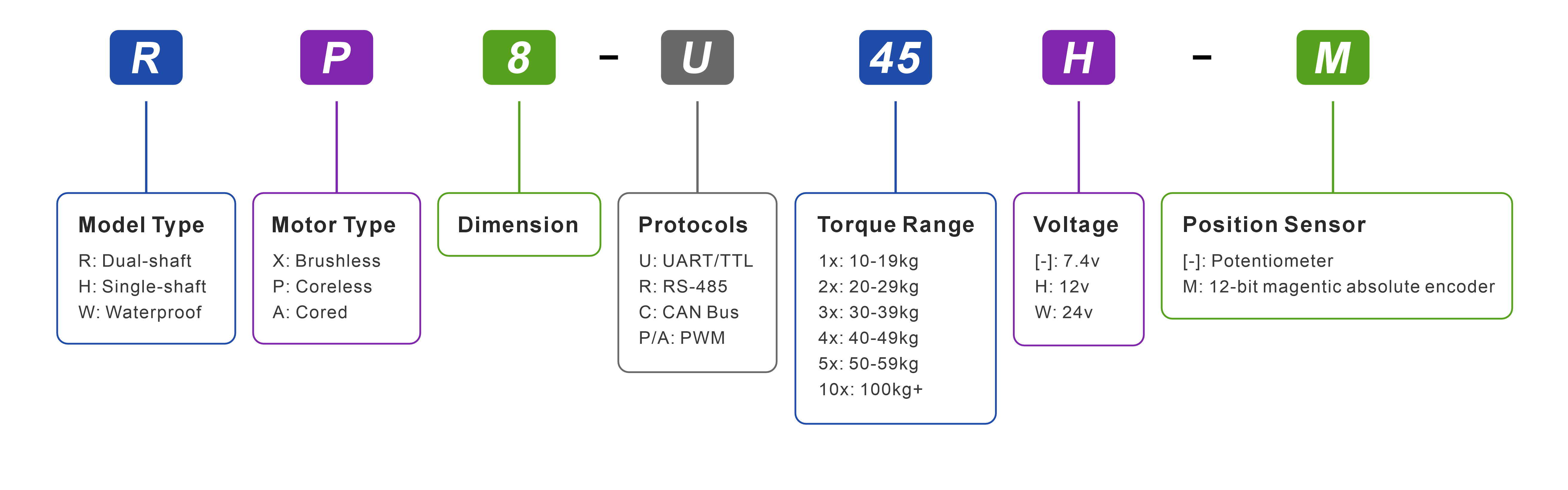
2. Model Naming
3. Specifications
3.1 Basic Specifications
| Parameter |
Value |
| Protocol Type |
CAN Bus |
| Input Voltage |
18.0 ~ 25.2 V |
| Motor Type |
Brushless |
| Position Sensor |
12-bit Contactless Absolute Encoder (Magnetic) |
| Effective Position Range |
±180° (single-turn) / ±368,640° (multi-turn) |
| Resolution |
4,096 counts / 360° (0.088° per count) |
| Processor |
32-bit MCU |
| Baud Rate |
9,600 bps ~ 1 Mbps |
| ID Range |
0 ~ 254 |
| Gear Ratio |
387:1 |
| Output Spline Specification |
Stainless Steel / Ø6 mm / 25T |
| Gear Material |
All Stainless Steel Construction |
| Interface |
PH2.0 - 4Pin |
| Case Material |
CNC All-Metal Housing |
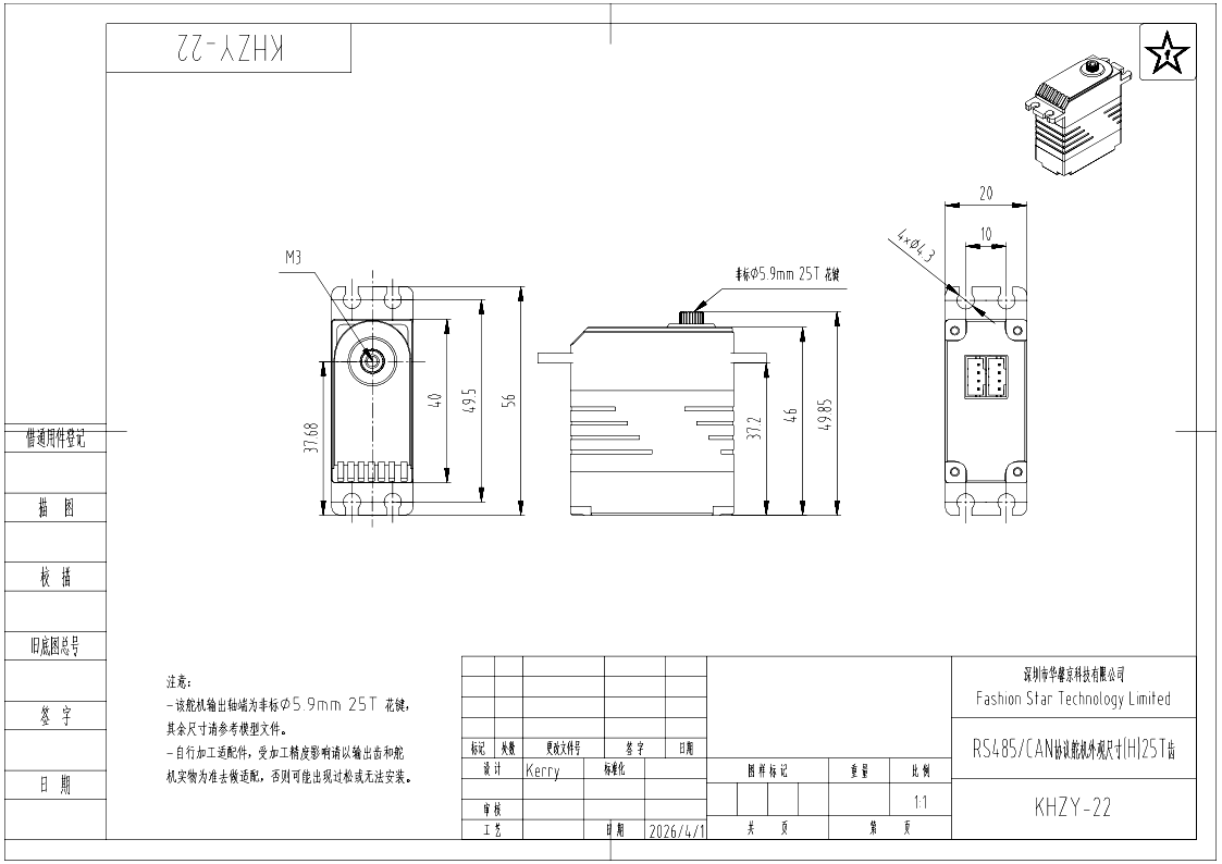
| Dimensions |
40 x 20 x 46 mm |
| Appearance |
Single-shaft |
| Weight |
96 g |
| Operating Temperature |
-10 ~ 60 °C |
| Operating Mode |
Single-turn Angle | Multi-turn Angle | Damping Mode |
| Parameter |
Value |
| Max Stall Torque |
4.90 N·m (50 kg·cm) |
| Max Dynamic Torque |
2.75 N·m (28 kg·cm) |
| Rated Torque (Continuous) |
0.88 N·m (9 kg·cm) |
| Rated Speed |
52 rpm (0.192 sec @ 60°) |
| No-Load Speed |
66 rpm (0.151 sec @ 60°) |
| Peak Current |
3 A |
| No-load Current |
<300 mA |
| Standby Current |
<40 mA |
| Axial Load |
20 N |
| Radial Load |
40 N |

T-N Characteristic Curve

Mechanical Overload Curve
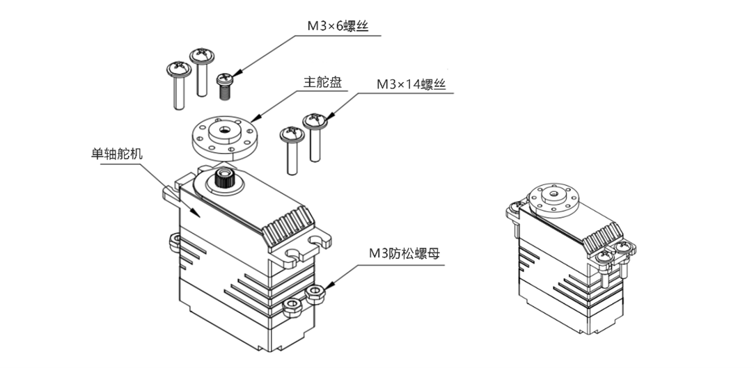
4. Dimensions & Installation
Downloads:
PDF |
STEP |
DWG|
More Part Drawings
5. Interfaces & Wiring

CAN Interface Pin Definition
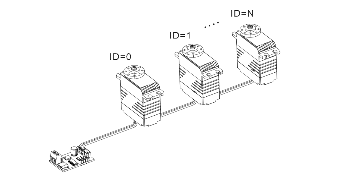
Daisy-Chain
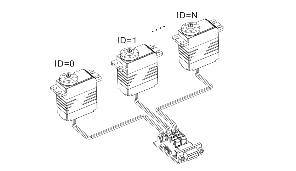
Parallel Connection
6. Protection Features
Bus servos integrate multiple protections for temperature, voltage, stall, power, and current. The status flag bits can be used to determine which protection is currently triggered.
| Temperature Protection |
- Trigger:Operating temperature > configured threshold
- Action:Force low-power operation, limiting output while maintaining basic motion
- Recovery: when the temperature falls to the threshold minus 10 °C, automatic recovery
|
| Stall Protection |
- Trigger:Stall torque-release switch ON + current power > protection threshold
- Action:Automatically release holding torque to prevent long-term motor overload damage
- Recovery:No power cycle is required. Send Stop Command to restore normal operation
|
| Power Protection |
- Trigger:Stall torque-release switch OFF + current power > protection threshold
- Action:Limit operating power, reducing it to the configured stall-power ceiling
- Recovery: automatic recovery after the power load drops back to a safe range
|
| Voltage Protection |
- Trigger:Operating voltage is outside the configured high/low voltage range
- Action:Automatically release holding torque, with no torque output so the servo enters a free state
- Recovery:Power-cycle required, and the voltage must return to the normal range
|
| Current Protection |
- Trigger:Operating current > configured threshold
- Action:Automatically release holding torque as the final safety fallback
- Recovery: automatic recovery after the current drops below the threshold
|
Warning
- After voltage protection is triggered, you must power-cycle the servo before it can resume operation.
- Stall/power/current protections prevent overload damage. Setting thresholds too high may make protection ineffective.
- If temperature or current protection is triggered frequently, reduce the load or improve cooling and power supply.
- The default temperature protection threshold is 70 °C.
- Default voltage protection ranges: 7.4 V version: 6.0-8.4 V / 12 V version: 9.0-12.6 V / 24 V version: 20.0-25.2 V.
- Current protection can be combined with stall and power protection. If the first two protections are not triggered by the Master / PC Software, current protection serves as the final hardware-level safeguard.
7. Communication Specifications
CAN bus servos use Classical CAN communication. The target servo is selected by ServoID, and device parameters are accessed using general read and write commands. For complete parameter addresses, data types, packet formats, and communication examples, see the CAN Bus Servo Communication Protocol.
7.1 CAN Communication Specifications
| Item |
Specification |
| Communication Protocol |
Classical CAN |
| Frame Format |
CAN 2.0A, 11-bit standard data frame |
| CAN ID |
Fixed at 0x321 |
| Default Baud Rate |
500 Kbps |
| Baud Rate Range |
9,600 bps–1 Mbps |
| ServoID Range |
0–254 (0x00–0xFE) |
| Data Length per Frame |
Maximum 8 bytes |
| Byte Order |
Little-endian, low byte first |
This protocol does not use extended frames, remote frames, or CAN FD.
7.2 Parameter Read and Write Methods
CAN servos use general commands to access device parameters. Motion control, status reading, and parameter configuration are all performed through the corresponding parameter addresses.
| Operation |
Description |
| Read Single Parameter |
Reads one 16-bit parameter at a time |
| Read Two Parameters |
Reads two 16-bit parameters at a time |
| Write Single Parameter |
Writes one 16-bit parameter at a time |
| Write Two Parameters |
Writes two 16-bit parameters at a time |
| Write and Return |
Returns the parameter value actually accepted by the servo after writing |
| Continuous Write |
Buffers multiple parameter groups and submits them together, suitable for writing combined parameters to a single servo |
A 32-bit parameter consists of two adjacent 16-bit addresses. The lower address stores the lower 16 bits, and the higher address stores the upper 16 bits. Signed parameters such as angles are represented using two's complement.
8. Motion and Control Commands
8.1 Communication Check
Read a device parameter from the target ServoID and use the response packet to determine whether the servo is online.
| Command |
Description |
| Communication Check |
A normal response containing the target servo's device parameter indicates that the servo is online |
8.2 Single-Turn Angle Control
- Supports time-based and speed-based control, and allows the servo's current single-turn angle to be read.
- The control range is ±180°, with a minimum control resolution of 0.1°.
| Command |
Parameters |
| Basic Single-Turn Angle Control |
Target angle, motion time, operating power |
| Advanced Single-Turn Angle Control (Time-Based) |
Target angle, motion time, acceleration time, deceleration time, operating power |
| Advanced Single-Turn Angle Control (Speed-Based) |
Target angle, motion speed, acceleration time, deceleration time, operating power |
| Read Single-Turn Angle |
Response packet = current servo angle |
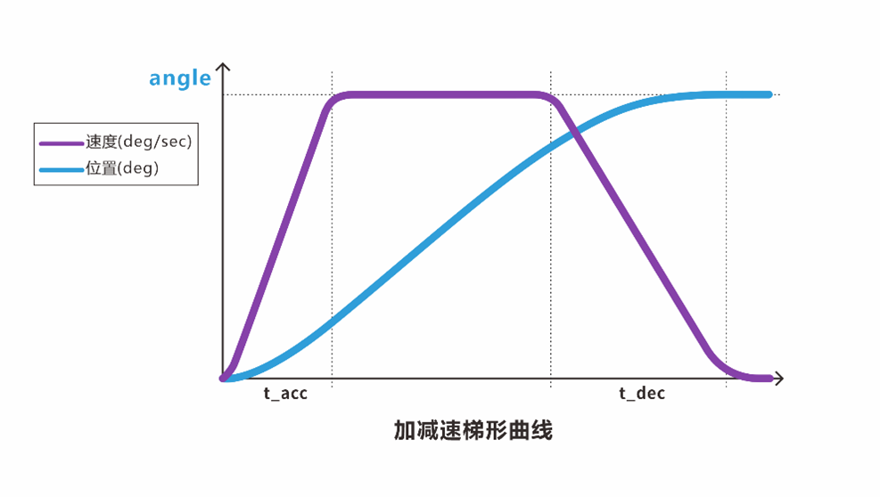
Trapezoidal Acceleration and Deceleration
8.3 Multi-Turn Angle Control
- Supports time-based and speed-based control, and allows the servo's current multi-turn angle to be read.
- The control range is ±368,640° (±1,024 turns), with a minimum control resolution of 0.1°.
| Command |
Parameters |
| Basic Multi-Turn Angle Control |
Target angle, motion time, operating power |
| Advanced Multi-Turn Angle Control (Time-Based) |
Target angle, motion time, acceleration time, deceleration time, operating power |
| Advanced Multi-Turn Angle Control (Speed-Based) |
Target angle, motion speed, acceleration time, deceleration time, operating power |
| Read Multi-Turn Angle |
Response packet = current servo angle |
Trapezoidal Acceleration and Deceleration
8.4 Turn Count Reset / Power-Off Angle Memory
Turn Count Reset
- When the servo is in the torque-released state, the turn count can be reset through the PC software or a designated command, recording the current absolute position angle as the current angle again.
- After the reset, the initial angle falls within the range of -180° to +180°.
| Command |
Description |
| Reset Turn Count |
Clears the current multi-turn count and records the current position again |
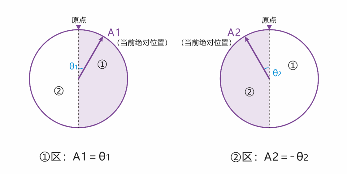
Turn Count Reset
As shown, the current angle at point A1 is 6,880°, and the angle after reset is θ1. The current angle at point A2 is 6,800°, and the angle after reset is -θ2.
Power-Off Angle Memory
- If the servo's angle does not change after power-off, the current angle read after power is restored remains unchanged. For example, if point A is at 6,800° before power-off and the angle does not change while power is off, the servo remains at point A and the angle read after power-on is still 6,800°.
- If an external force changes the servo angle after power-off, the angle read after power is restored will fall within ±180° of the memorized angle.
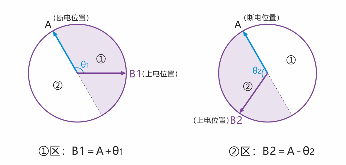
Power-Off Angle Memory
As shown, point A is at 6,800° before power-off. If an external force moves the servo while power is off and it stops at point B1, the angle read after power-on is 6,920°. If it stops at point B2, the angle read is 6,680°.
8.5 Damping Mode
Allows the servo to move to different angular positions under an external force while maintaining a specified damping effect. The damping coefficient can be customized.
| Command |
Parameter |
| Damping Control |
Operating power (mW) |
8.6 Stop Commands
- Select the appropriate stop-command type according to the motion-control requirements. See the table below for details.
- A stop command can also restore normal operation after stall protection has been triggered.
- When the servo is in the torque-released state, sending the "Hold Torque" command restores holding torque at the current position.
| Command |
Description |
| Release Torque |
Stops motion and releases holding torque. |
| Hold Torque |
Stops motion and maintains holding torque, or restores holding torque from a torque-released state. |
| Hold Damping |
Stops motion and enters damping mode, allowing an external force to adjust the angle. |
8.7 Status Reading / Data Monitoring
Retrieves the servo's operating status and key parameters for debugging, inspection, and real-time display in the PC software.
| Command |
Description |
| Data Read |
Reads an individual servo status or configuration parameter and returns its value. |
| Data Monitoring |
Reads information such as voltage, current, power, temperature, status bits, angle, and turn count. |
8.8 Set Origin
Sets the servo's current position as the origin. This is commonly used for zero-position calibration after assembly and provides a consistent motion starting reference for control algorithms.
| Command |
Parameter |
| Set Origin |
Servo ID / reset = 0 |