Integrating Bus Servos with Inovance AM401 PLC Using InoproShop
This guide explains how to integrate Fashion Star bus servos with an Inovance AM401 PLC using InoproShop. It covers serial configuration, library import, angle control, position readback, and asynchronous commands.
1. Wiring Instructions
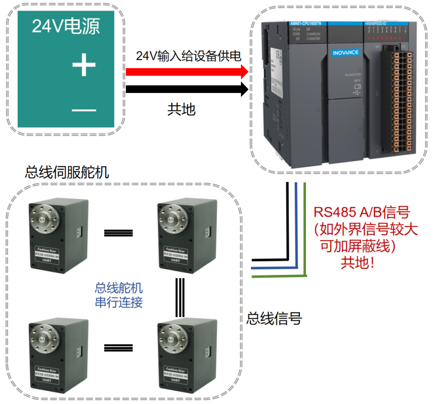
1.1 Servo Wiring
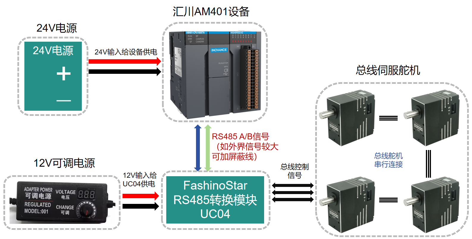
1.2 RS-485 Servo Wiring
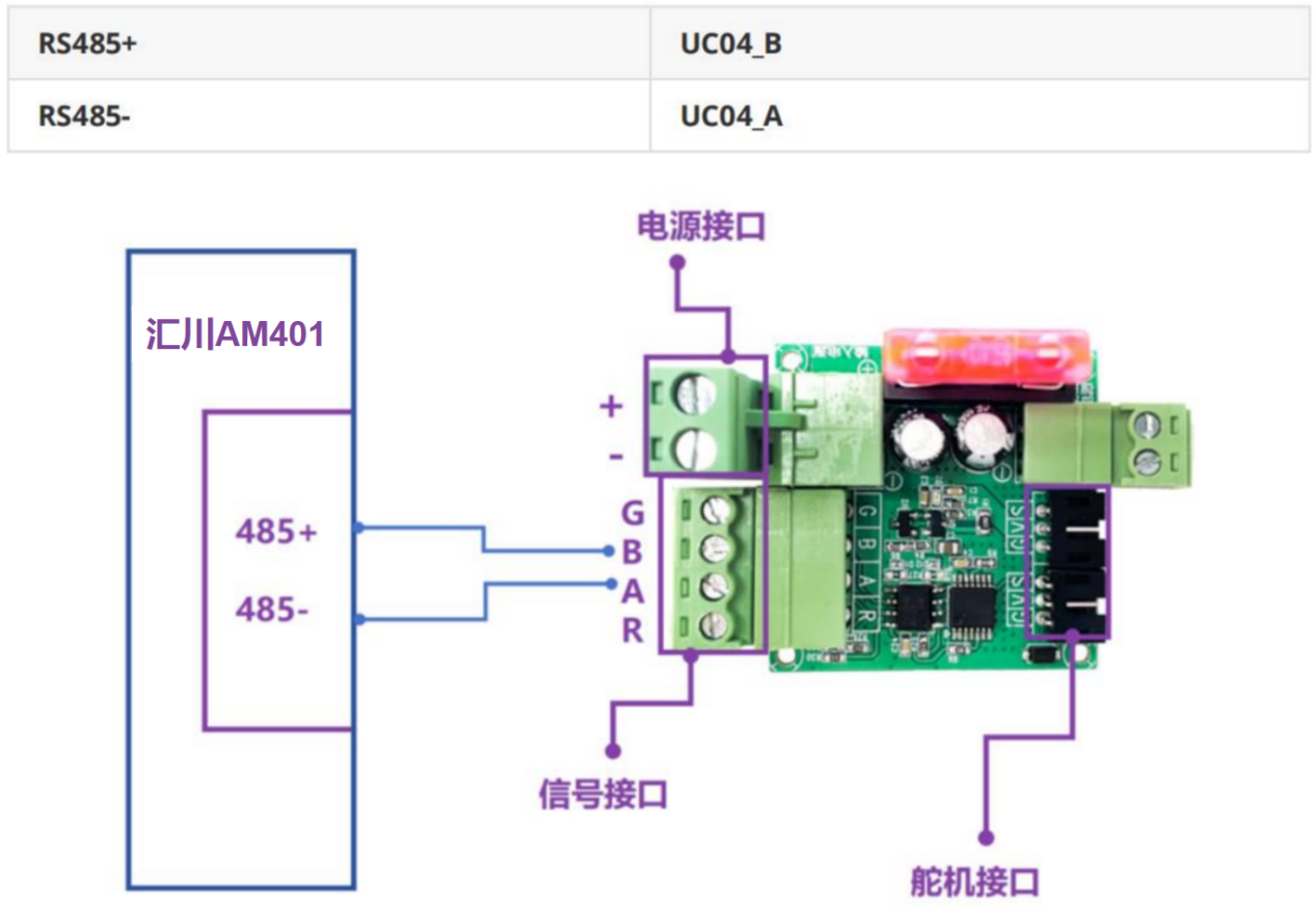
1.3 UC04 Wiring
2. Program Instructions
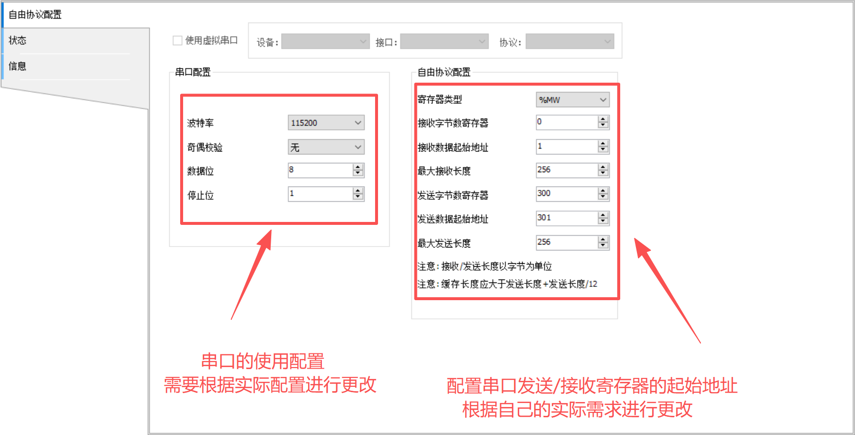
2.1 PLC Serial Port and Free Protocol Configuration
(1) Serial port configuration (default):
- Baud rate: 115200
- Parity: None
- Data bits: 8
- Stop bits: 1
(2) Free protocol example:
- Receive byte-count register:
%MW0/%MB0 - Receive data start address:
%MW1/%MB2 - Max receive length: 256
- Send byte-count register:
%MW300/%MB600 - Send data start address:
%MW301/%MB602 - Max send length: 256
2.2 Serial Data Write (via Function Block Library)
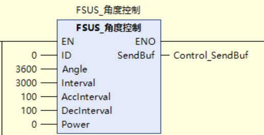
- 0 ------- Servo ID
- 3600 -- Target angle 360.0°
- 3000 -- Reach target in 3000ms (3s)
- 100 ---- Acceleration time 100ms
- 100 ---- Deceleration time 100ms
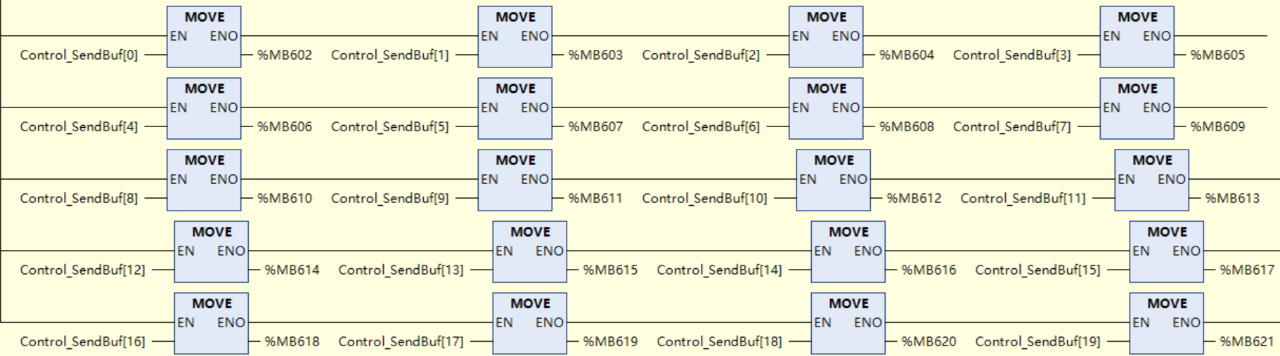
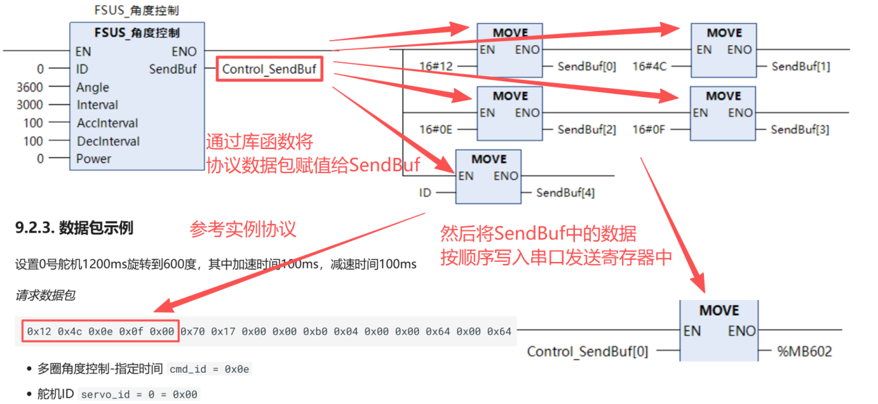
Use function blocks to convert and pack data into a custom send array,
then assign values from SendBuf to the serial send start address in order.
2.3 Serial Data Send
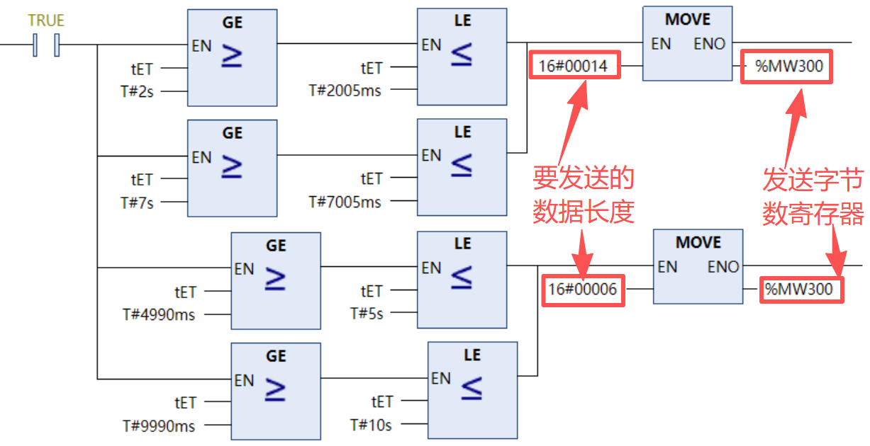
After protocol packet data is written to the serial send registers, set the send byte-count register to the number of bytes to send (non-zero) to transmit successfully. After successful transmission, the register is automatically reset to zero.
Reference for serial configuration:
Medium PLC Programming Manual (Software) - CN-C02.PDF
2.4 Function Block and Protocol Mapping
Protocol reference for Fashion Star bus servo communication:
https://fashionstar.com.hk/wiki/protocols/servo/uart-rs485/
3. Importing Library Files
- In InoproShop, go to the project tab and import all FB libraries via PLCopenXML.
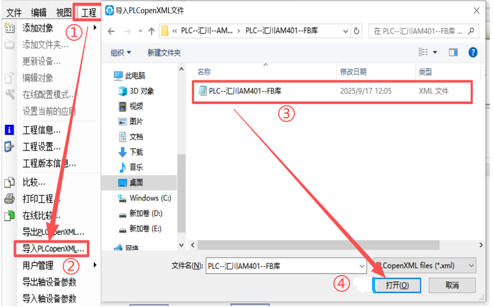
- After importing, drag function blocks from the toolbox and fill in required parameters.
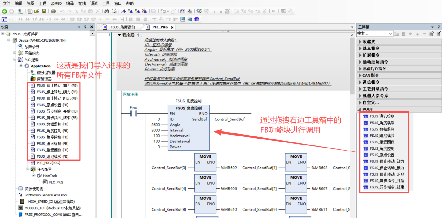
4. Function Block Description
4.1 Angle Control
- ID: servo ID
- Angle: target servo angle (3600)
- Interval: time to reach target angle
- AccInterval: acceleration time
- DecInterval: deceleration time
- Power: output power
Note: when writing SendBuf data to serial send registers, data must be sent sequentially and continuously. The send byte count must also be set to the actual packet length.
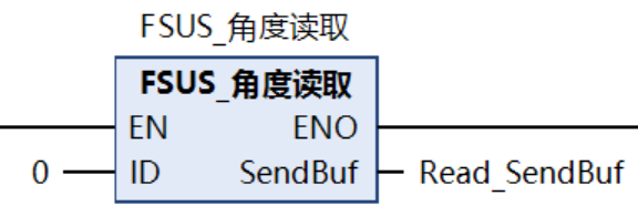
4.2 Angle Readback
- ID: servo ID
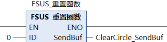
4.3 Turn Counter Reset
- ID: servo ID
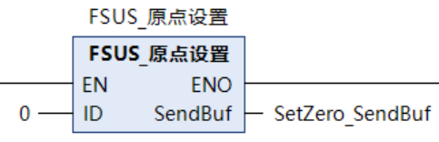
4.4 Home Position Set
- ID: servo ID
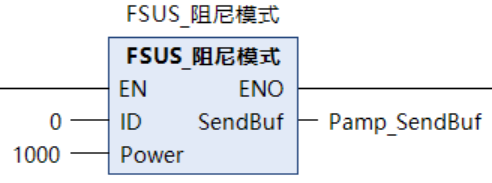
4.5 Damping Mode
- ID: servo ID
- Power: damping output power (mW)
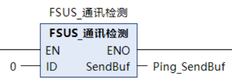
4.6 Communication Test
- ID: servo ID
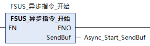
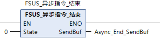
4.7 Async Commands
- Start async: fixed command, use directly.
- End async:
State: 0 -- execute immediately after ending async; 1 -- cancel execution after ending async.
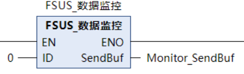
4.8 Data Monitoring
- ID: servo ID
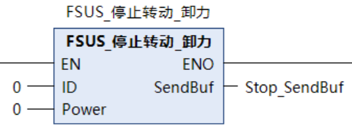
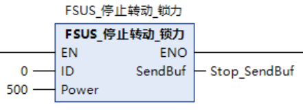
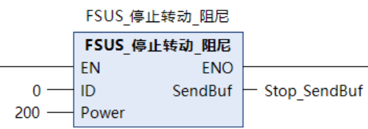
4.9 Stop Rotation (Three Modes: Release / Hold / Damping)
- ID: servo ID
- Power: output power (mW)