Bus Servo Configuration Software
| Version | Supported OS | Package |
|---|---|---|
| v1.1.9.288 | Windows | Download |
1. Video Tutorial
If the video fails to load, watch it on Bilibili.
2. Software Launch
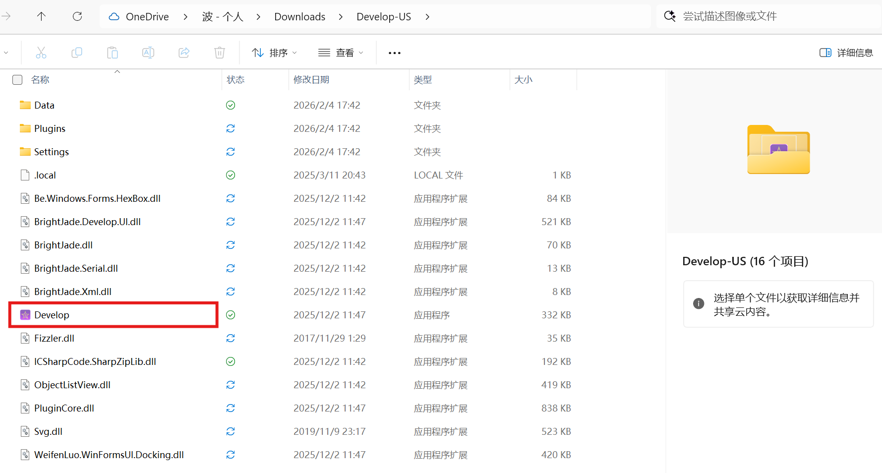
- This is a portable program and does not require installation. Extract the package and run
Develop.exedirectly.
3. Servo Connection and Detection
3.1 Physical Wiring
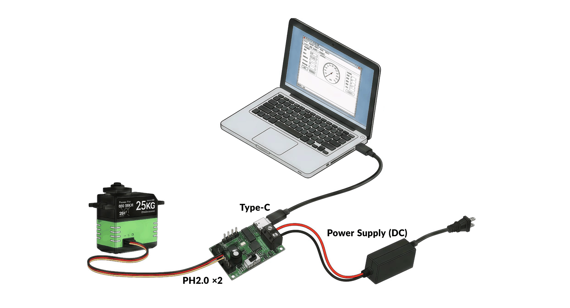
Complete the hardware connection between the servo and the computer in the following order:
- Connect the servo to the adapter board with a data cable.
- Connect the external power supply for the servo.
- Connect the adapter board to the computer with a USB cable.
Warning
The adapter board input voltage must match the power input range of the servo. Otherwise, voltage protection will be triggered and the system cannot operate normally.
3.2 Serial Port Connection
- Click Refresh Device in the upper-left corner to refresh the serial port list.
- Select the automatically detected adapter board serial port from the list, such as COM10.
- Click Switch to configure serial port parameters.
- Click Confirm to complete the serial port connection.
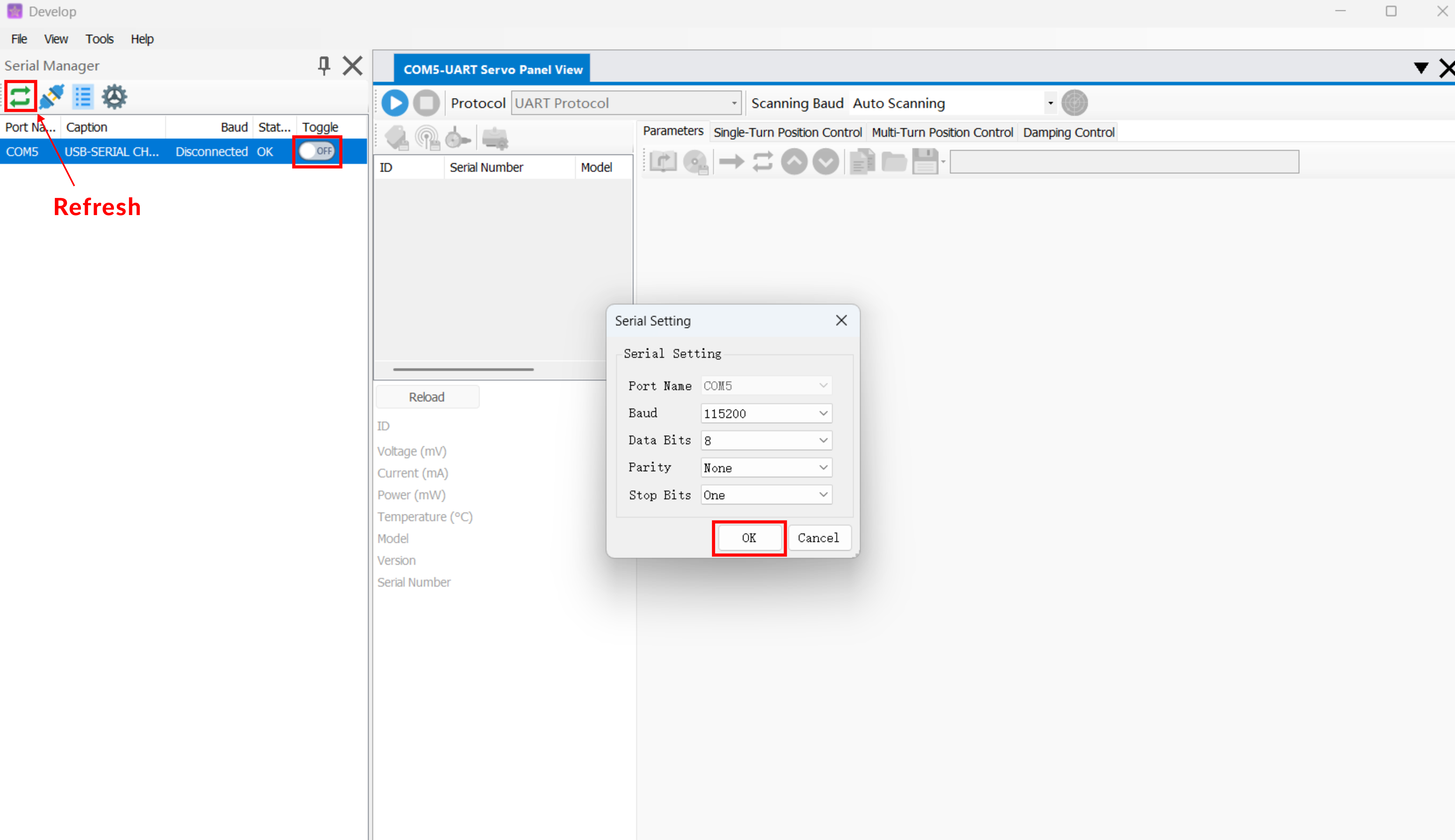
If the adapter board serial port information is not shown in the serial port list, the driver may not be installed correctly. Please download the CH340 driver, install it, and refresh the serial port list again.
3.3 Scan Servo
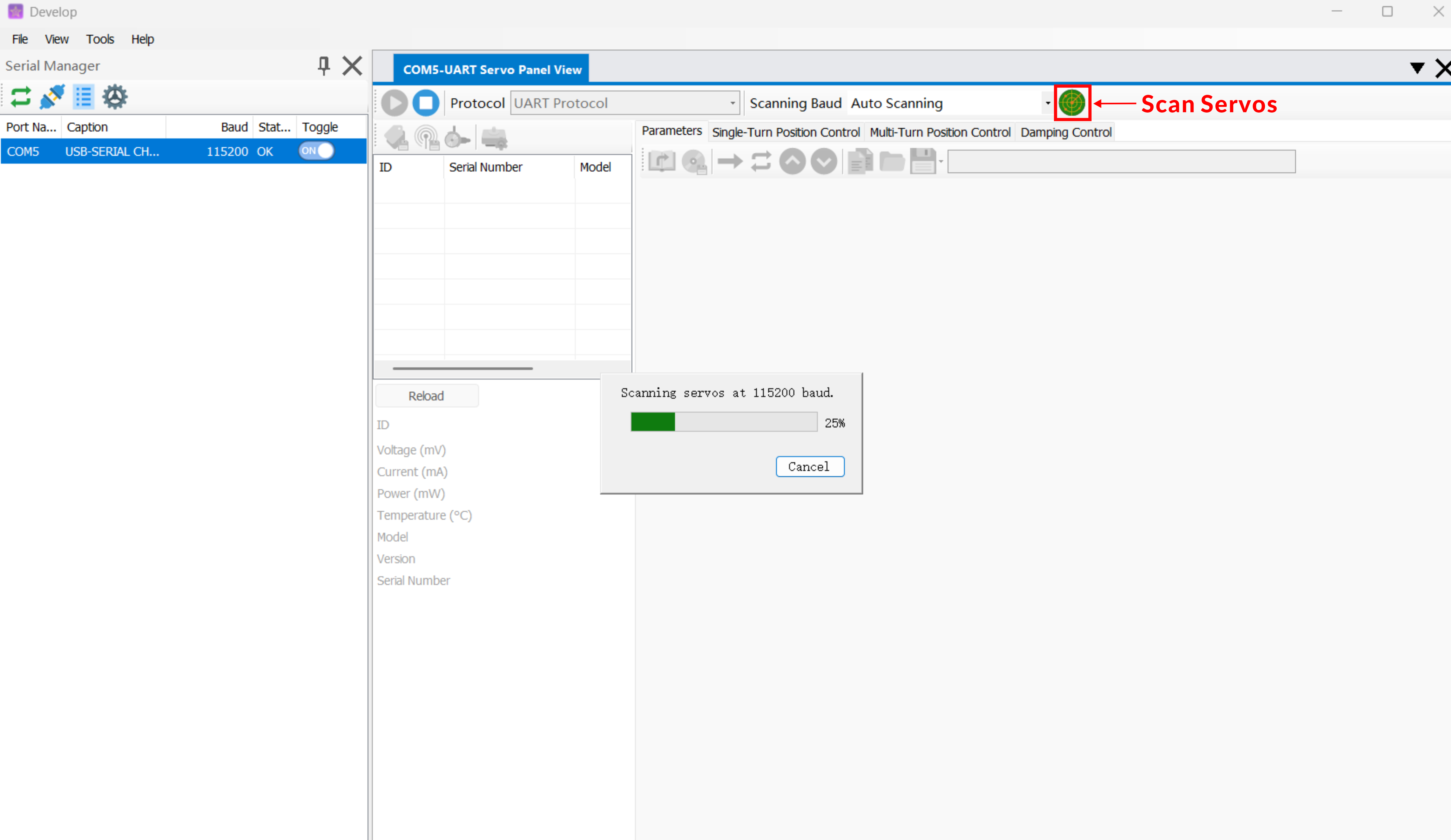
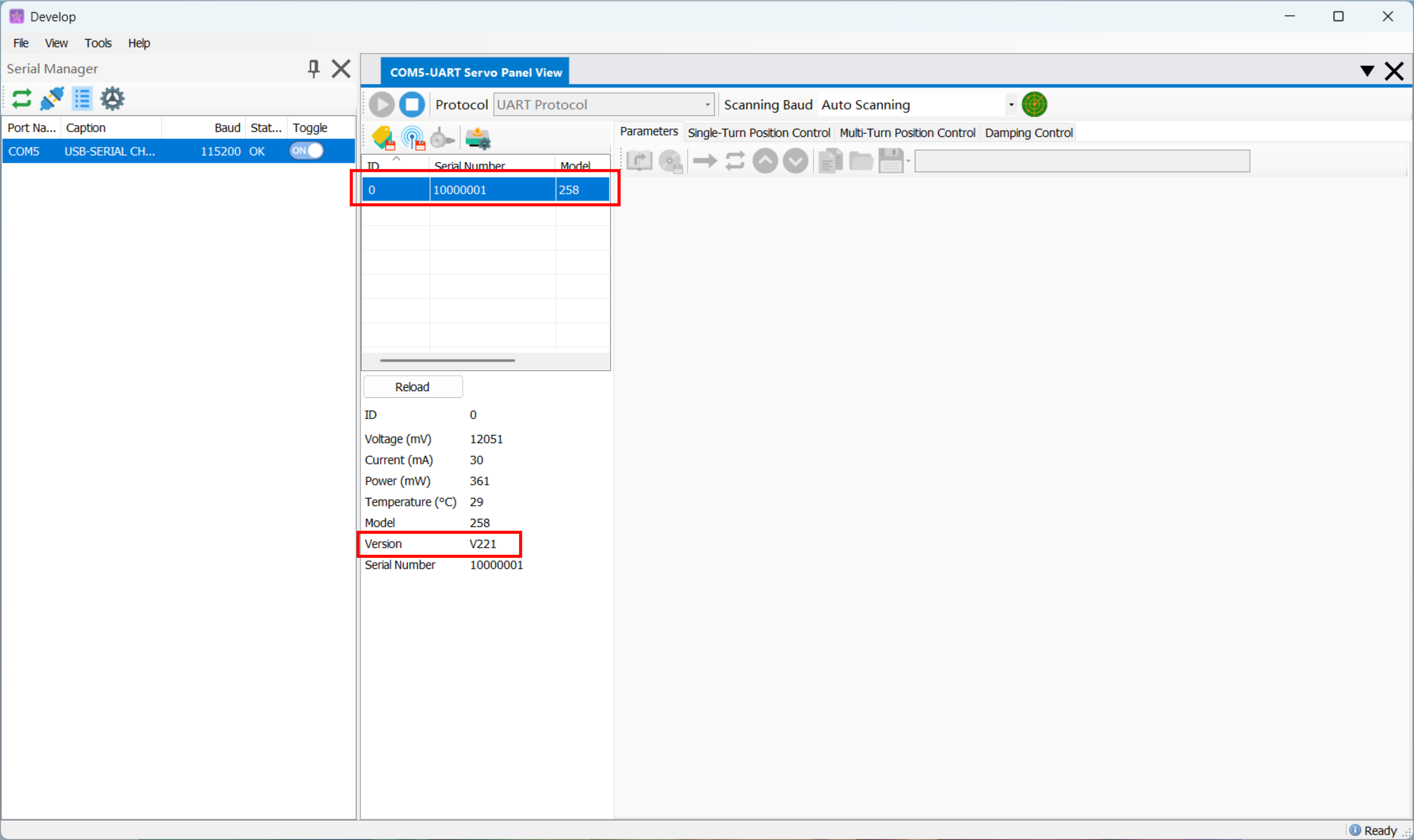
- 1. Click Scan servo. The software starts scanning automatically.
-
2. After scanning is complete, the middle list displays all found servo. Select them one by one to view the current operating status.
-
3. The list also shows servo firmware version information for later firmware upgrade reference.
4. Real-Time Control
4.1 Single-Turn Angle Control
- Click servo Control.
- Open the Single-Turn Angle Control tab.
- Set Control Mode parameters as needed. Enter the target angle and click Send; the servo moves to the target angle.
- Click Read Angle. The dialog box displays the current angle of the servo.
- Click Stop. The servo stops working and enters the selected stop mode.
- Click servo Control again to exit the current mode.
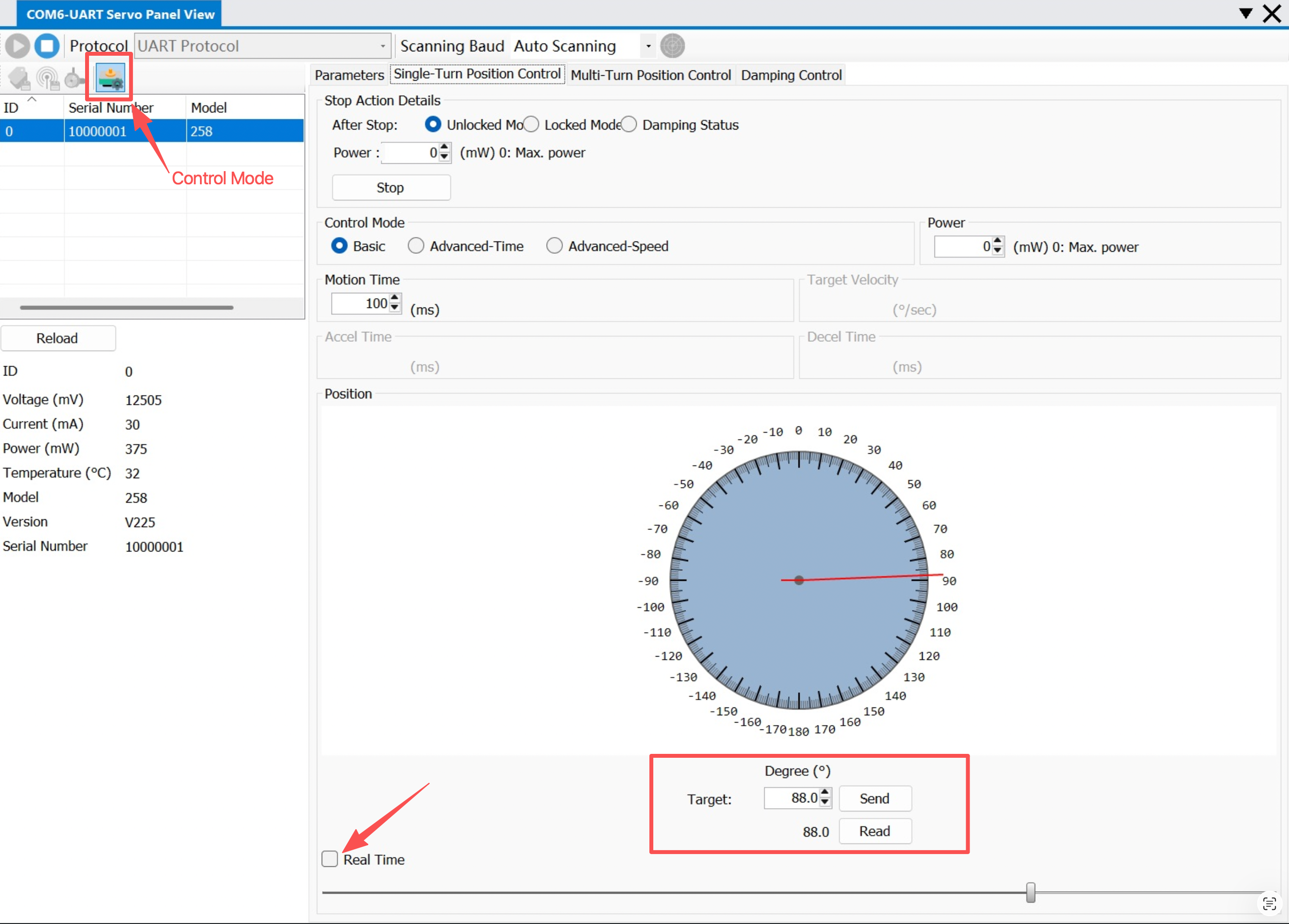
- First confirm that Real-Time Control is not checked.
- If Real-Time Control is checked, control is available only by dragging the slider below.
4.2 Multi-Turn Angle Control
- Click servo Control.
- Open the Multi-Turn Angle Control tab.
- Set Control Mode parameters as needed. Enter the target angle and click Send; the servo moves to the target angle.
- Click Stop. The servo stops working and enters the selected stop mode.
- Click servo Control again to exit the current mode.
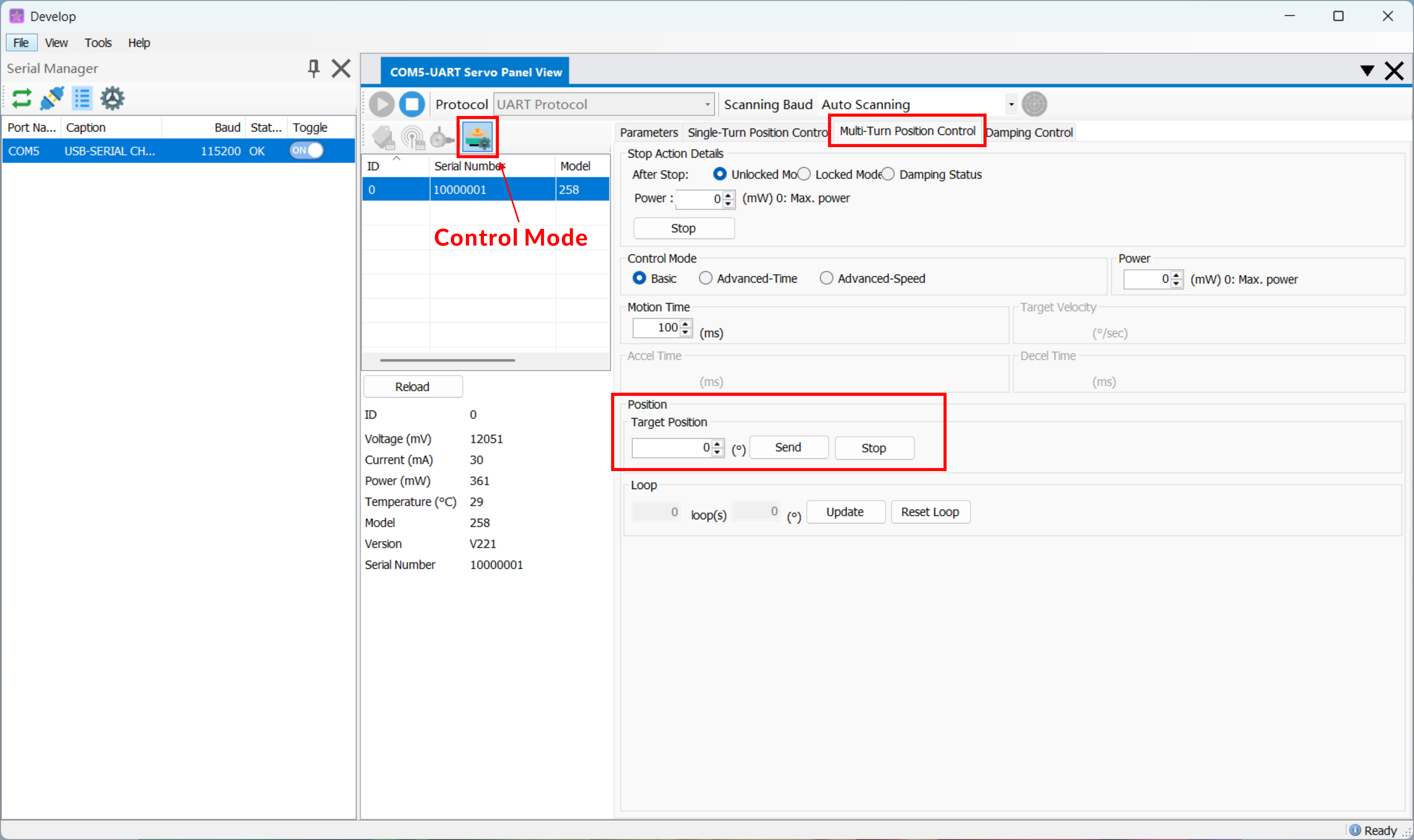
- Multi-turn mode does not support real-time drag control.
4.3 Read Multi-Turn Angle
- Click Servo Control.
- Open the Multi-Turn Angle Control tab.
- Click Update. The dialog box displays the current angle of the servo. When the angle is greater than 360°, it is displayed as Turns + Angle.
- Click servo Control again to exit the current mode.
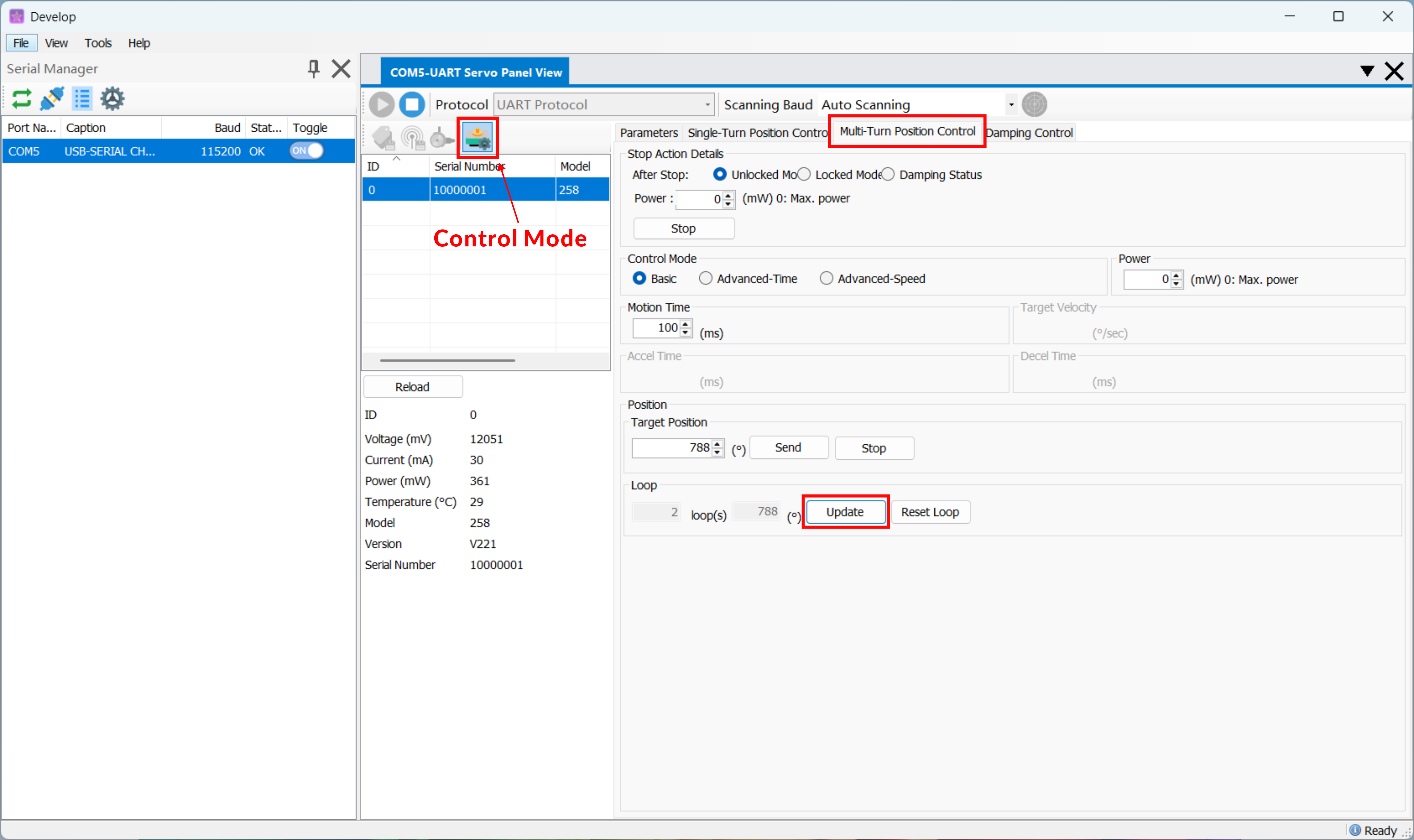
- To read the current angle in single-turn mode, use the Single-Turn Angle Control tab.
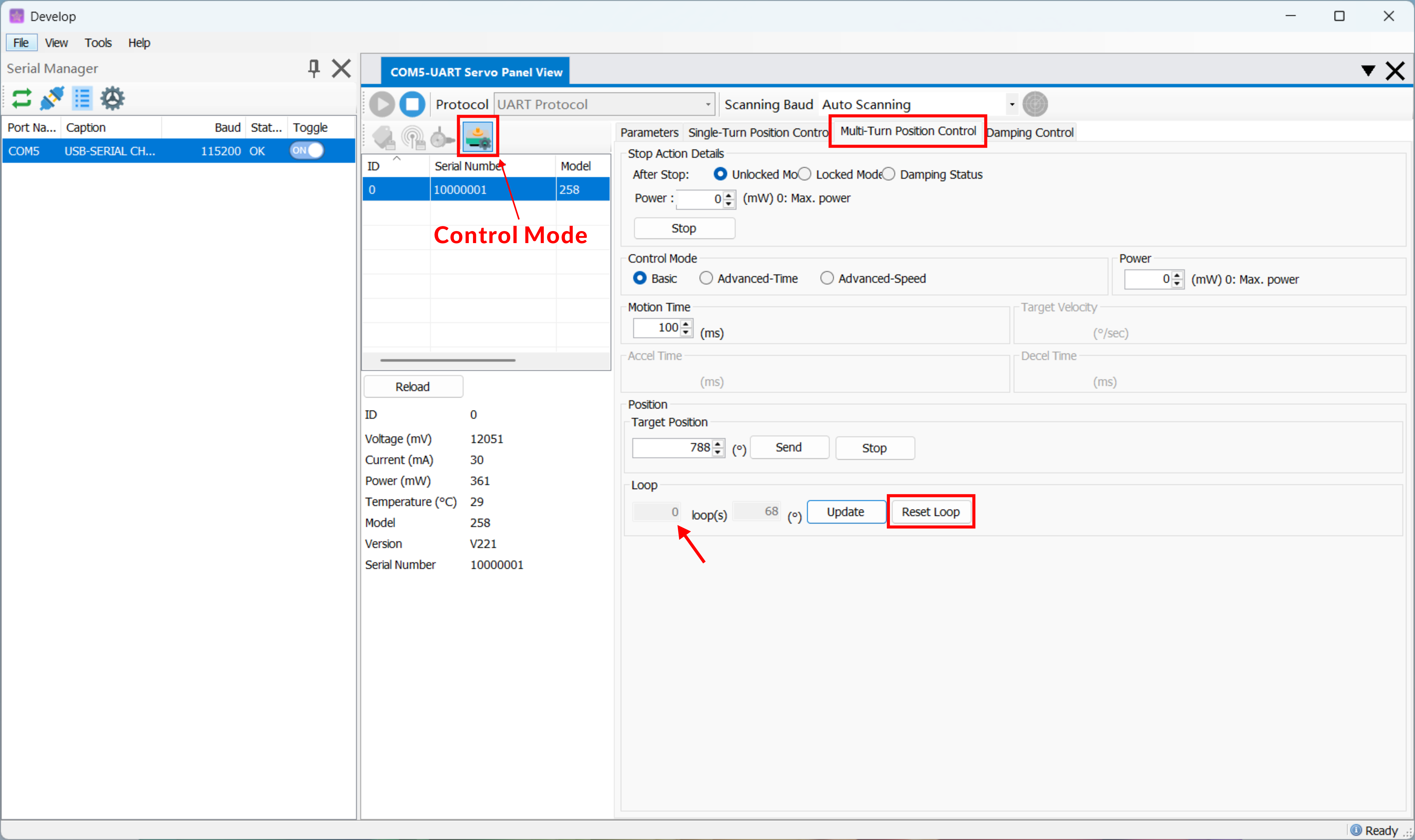
4.4 Reset Turn Count
- Click servo Control.
- Open the Multi-Turn Angle Control tab.
- Click Reset Turn Count to clear the turn-count information recorded by the servo. The current angle is retained.
- Click servo Control again to exit the current mode.
4.5 Damping Mode
- Click servo Control.
- Open the Damping Control tab.
- Set the Power parameter as needed and click Send. At this point, the servo produces a damping effect when rotated by external force.
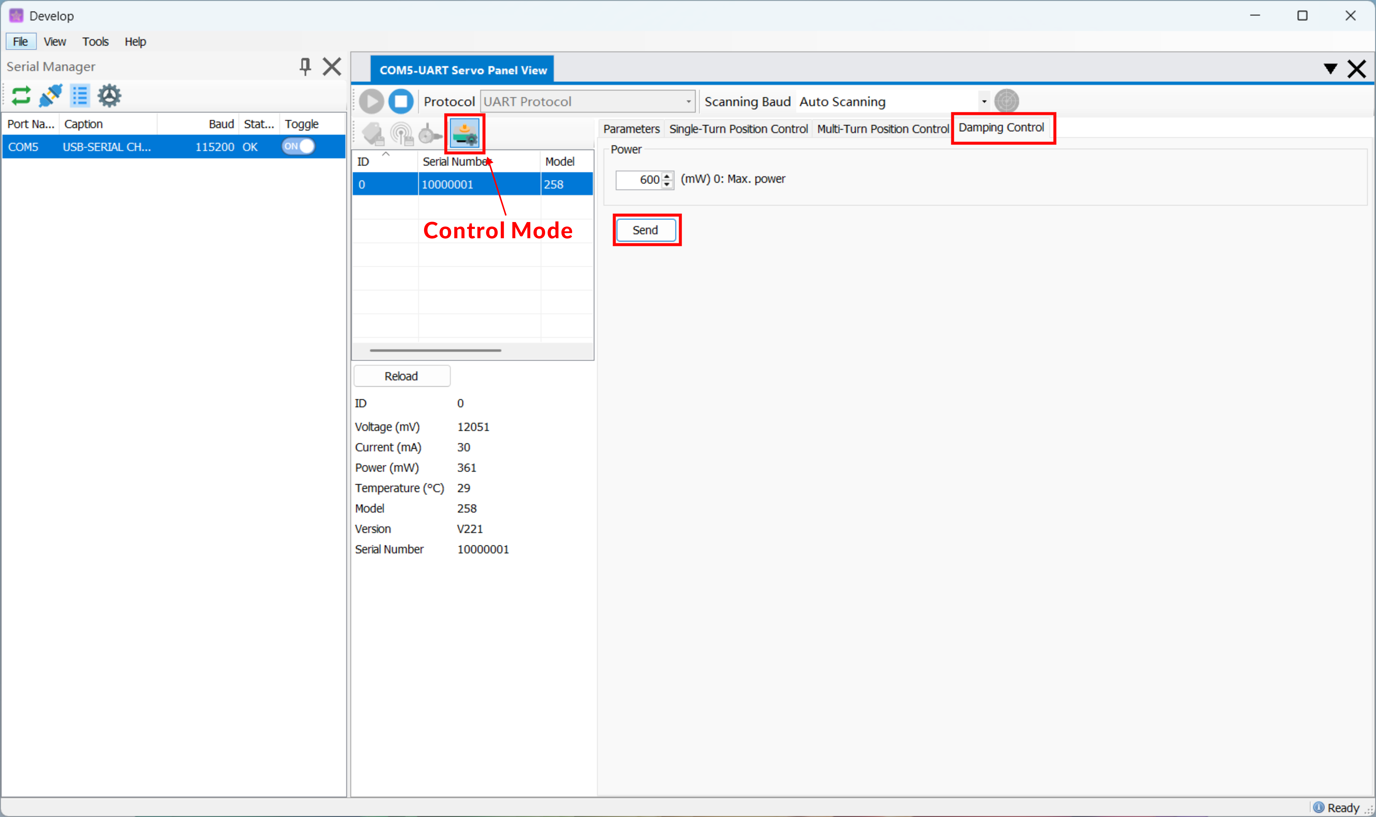
- Gear ratios differ between servo models. Start with 600mW, then fine-tune based on the actual effect.
5. Common Settings
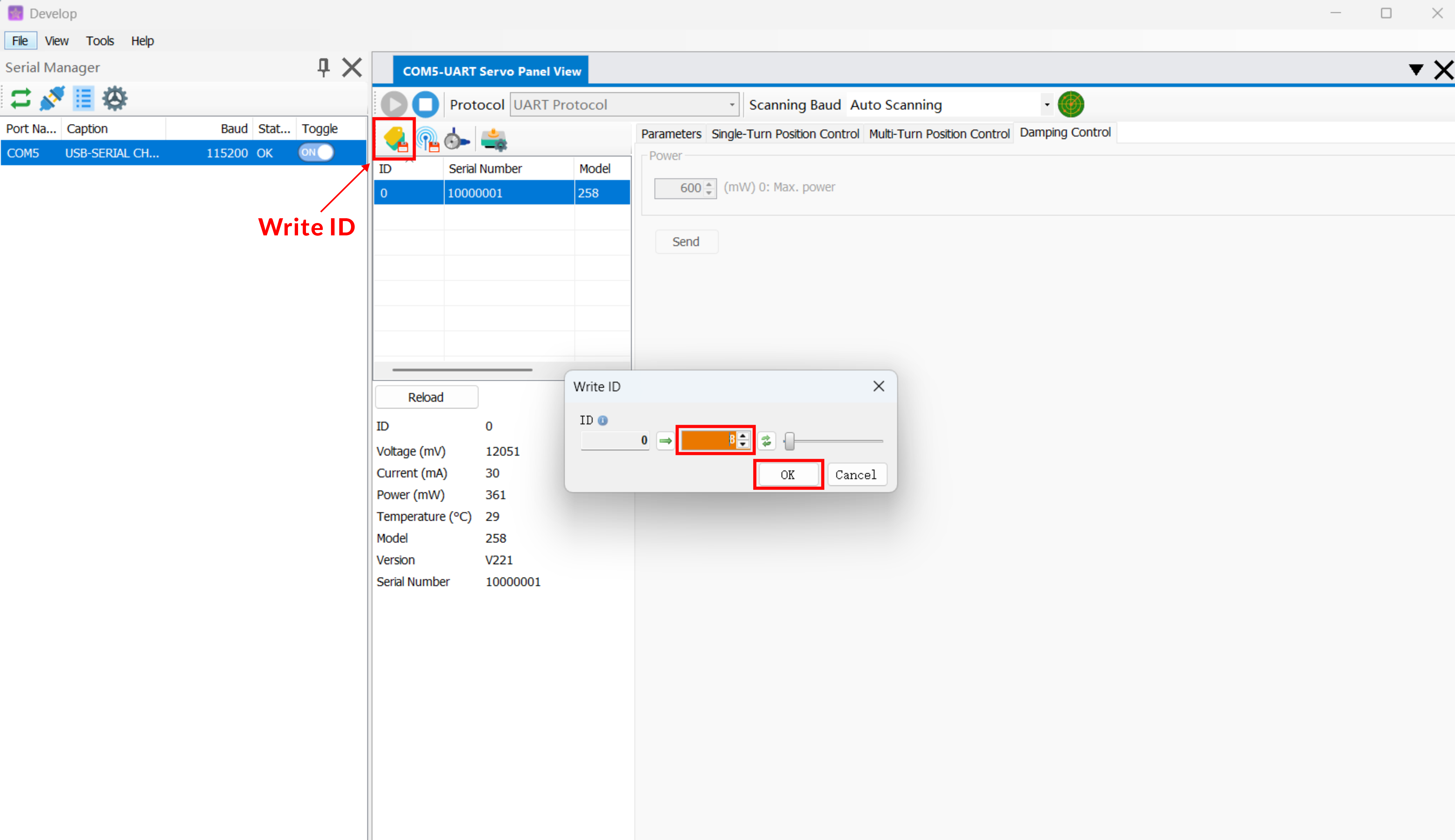
5.1 Change servo ID
- Select the servo to modify.
- Click Change servo ID and enter the new ID in the popup window.
- Click Confirm. The setting takes effect immediately.
5.2 Read/Write Parameters
5.2.1 Parameter Configuration Table
| Parameter | Description |
|---|---|
| Low-Voltage Protection Threshold (mV) | When the operating voltage of the servo is lower than this configured value, it automatically releases lock torque, outputs no torque, and enters the free state. Power must be cycled, and the voltage must return to the normal range. |
| High-Voltage Protection Threshold (mV) | When the operating voltage of the servo is higher than this configured value, it automatically releases lock torque, outputs no torque, and enters the free state. Power must be cycled, and the voltage must return to the normal range. |
| Stall Unlock Protection | When Stall Unlock Protection = ON and the current power of the servo exceeds the Power Protection Threshold, the servo automatically releases lock torque. Power cycling is not required; sending a stop command restores operation. |
| Power Protection Threshold (mW) | Power protection threshold. When exceeded, the corresponding stall protection or power protection behavior is executed. |
| Stall Power Upper Limit (mW) | When Stall Unlock Protection = OFF and the current power of the servo exceeds the Power Protection Threshold, the servo lowers output to this configured power level. |
| Current Protection Threshold (mA) | When the operating current of the servo exceeds this configured parameter, it automatically releases lock torque as end-effector safety redundancy. It automatically resumes operation after the current falls below the threshold. |
| Temperature Protection Threshold (°C) | When the operating temperature of the servo exceeds this configured parameter, it enters forced low-power operation, limiting output while maintaining basic motion. When the servo temperature drops to the configured value - 10°C, it automatically resumes operation. |
| Angle Limit | Angle limit switch. When enabled, angle motion is constrained by the upper/lower limits. When disabled, no limit is applied. |
| Upper Angle Limit (°) | Maximum allowed angle value. Values above this limit are constrained to the upper limit. |
| Lower Angle Limit (°) | Minimum allowed angle value. Values below this limit are constrained to the lower limit. |
| Soft Start on Power-Up | After power-up, output starts slowly and gradually increases to reduce impact and jitter. |
| Lock Torque on Power-Up | After power-up, lock torque is applied automatically to hold the current position. |
| Respond After Command Is Sent | Default: OFF. Only commands with fixed responses return data. When enabled, configurable commands also return response data. |
Warning
- Parameter changes directly affect servo protection and operating behavior. Operate only under safe conditions.
- If you are unsure about a parameter's meaning or range, keep the default value first, or make a small adjustment and verify it.
Caution
- Internal parameters directly affect servo motion characteristics. Do not modify them unless necessary. If adjustment is required, refer to the xxx article or contact technical support first and operate under guidance.
5.2.2 Read Parameters
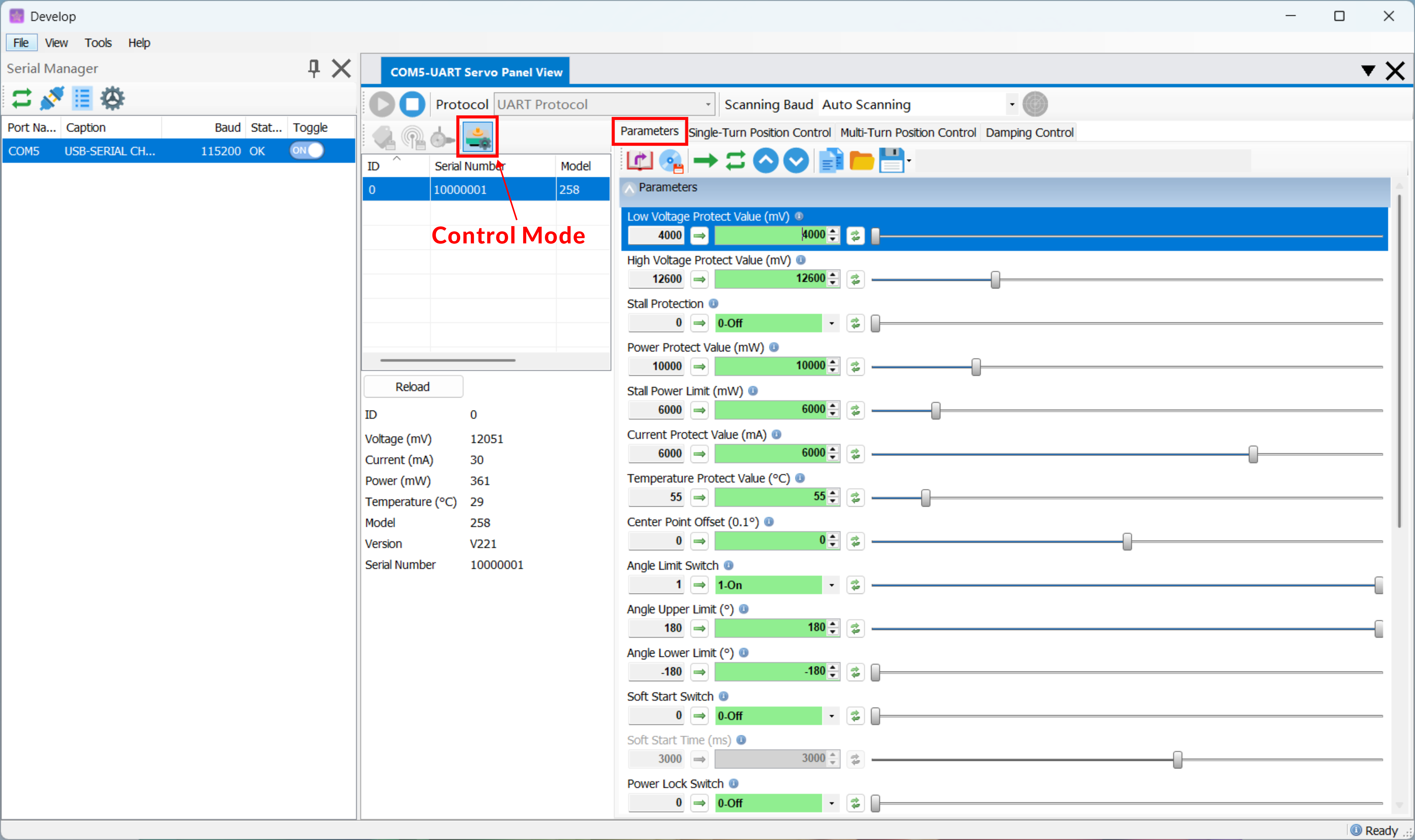
- Click serial port Control.
- Open the Parameters tab.
- The left panel with a gray background displays the current parameter configuration of the serial port.
5.2.3 Write Parameters
- Click serial port Control.
- Open the Parameters tab and select the configuration item to modify.
- Adjust the parameter in the right panel to the target value.
- Click Write Parameters to apply the parameter.
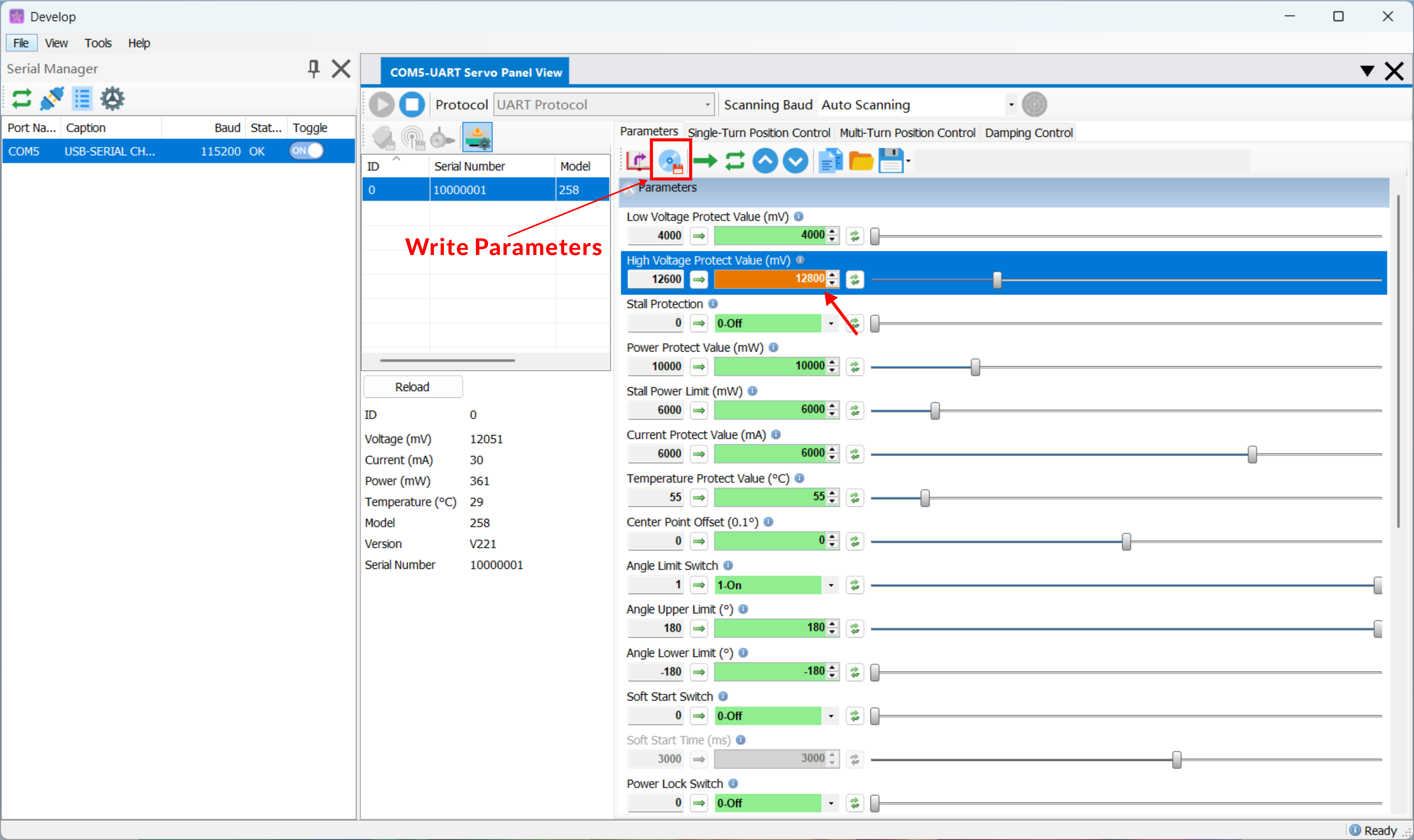
- Modified parameters are marked with an orange background. Confirm them carefully before writing parameters.
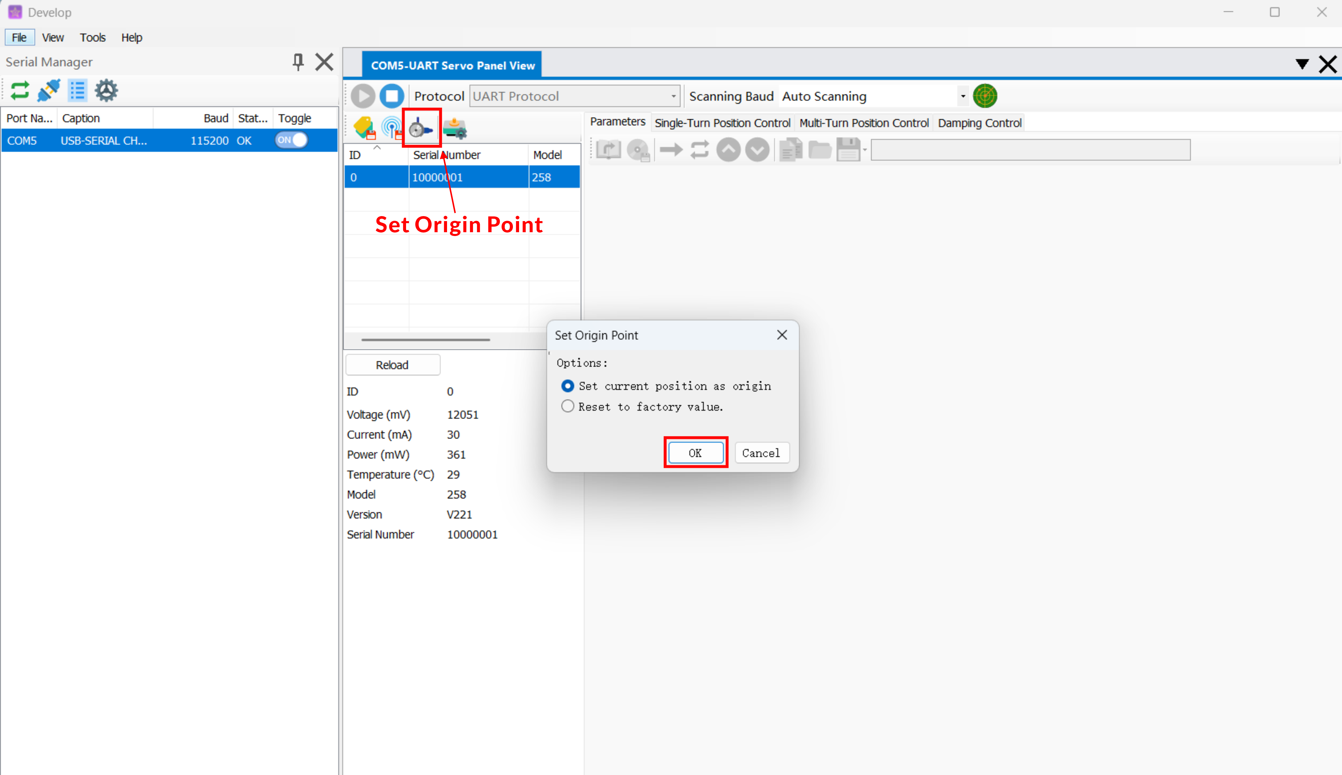
5.3 Origin Setting
The serial port origin is already calibrated before shipment. If required for assembly or program adaptation, any position can be redefined as the origin.
- Manually rotate the servo output shaft to the position that should be set as the origin.
- Click Origin Setting.
- Select Set Current Position, then click Confirm.
Warning
- The newly set origin takes effect only after power is cycled.
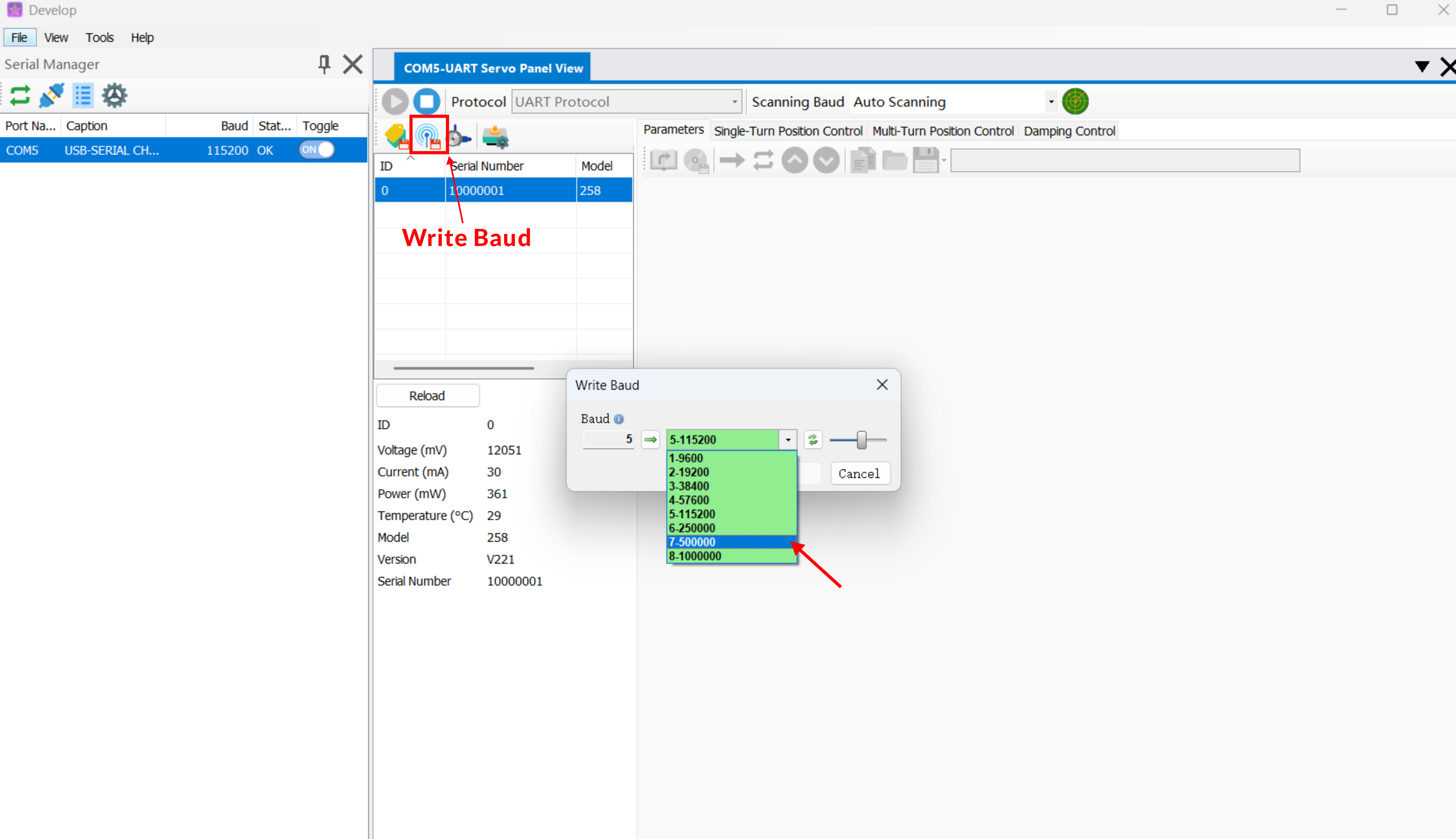
5.4 Change Baud Rate
- Select the servo to modify.
- Click Write Baud Rate and select the desired baud rate option in the popup window.
- Click Confirm. The software automatically scans for servos again and finds the servo at the modified baud rate.
5.5 Change ID Scan Range
- To improve scan efficiency, the default ID scan range of the software is #0-30.
- To change the scan range, go to Tools / Settings / Change Scan Range.
6. FAQs and Troubleshooting
No servo is found during scanning.
- Confirm that the adapter board is connected to power. USB alone cannot detect it.
- Confirm that the power supply voltage is within the operating range of the servo. Too high or too low a voltage can cause detection failure.
- Do not connect multiple servos with the same ID at the same time. Change them to different IDs separately before connecting them together.
The adapter board serial port is not shown.
- If the adapter board serial port information is not shown in the serial port list, the driver may not be installed correctly.
- Please download the CH340 driver, install it, and refresh the serial port list again.
The servo does not move smoothly during real-time drag control.
- Open the servo Parameter Configuration option and confirm that Respond After Command Is Sent is OFF.
- If it is not OFF, turn it OFF, write the parameters, and try again.