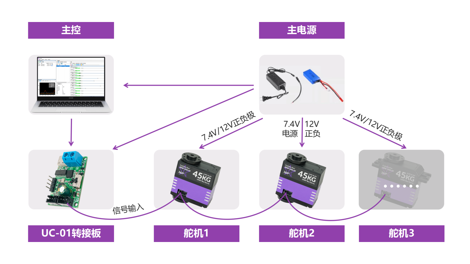
Wiring and Power Supply Solutions
1. Wiring Methods
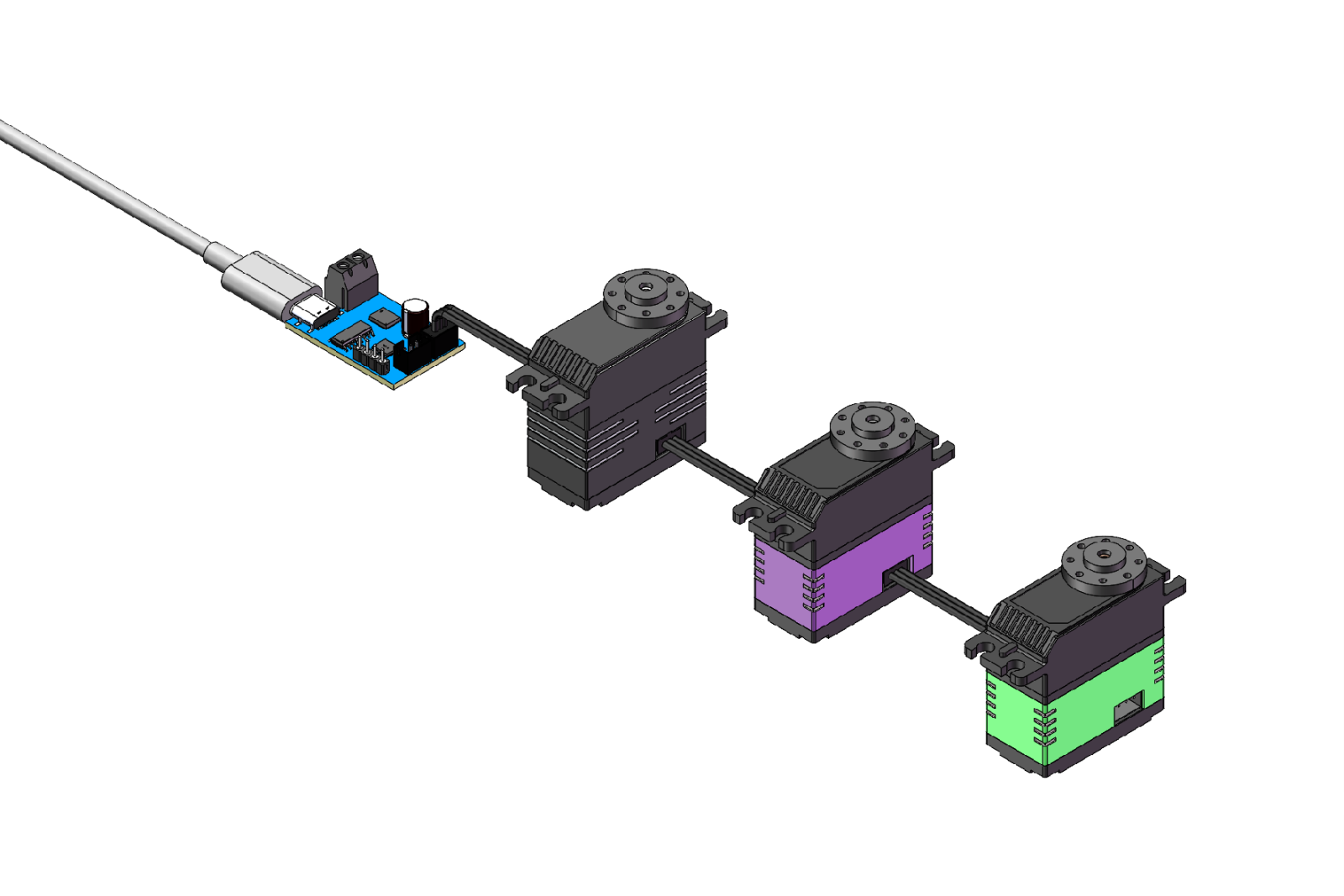
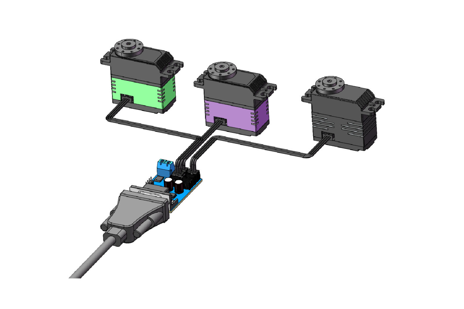
bus servo units can be wired flexibly using daisy-chain, parallel connection, and combined daisy-chain and parallel connection depending on device placement and wiring requirements, enabling a clean wiring layout.
2. Power Supply Solutions
Considering the power demand of each servo, long cable runs, and the current capacity of the data cable, the following power supply schemes help ensure sufficient power delivery to the servo units while improving power distribution.
2.1 Standard Wiring Scheme
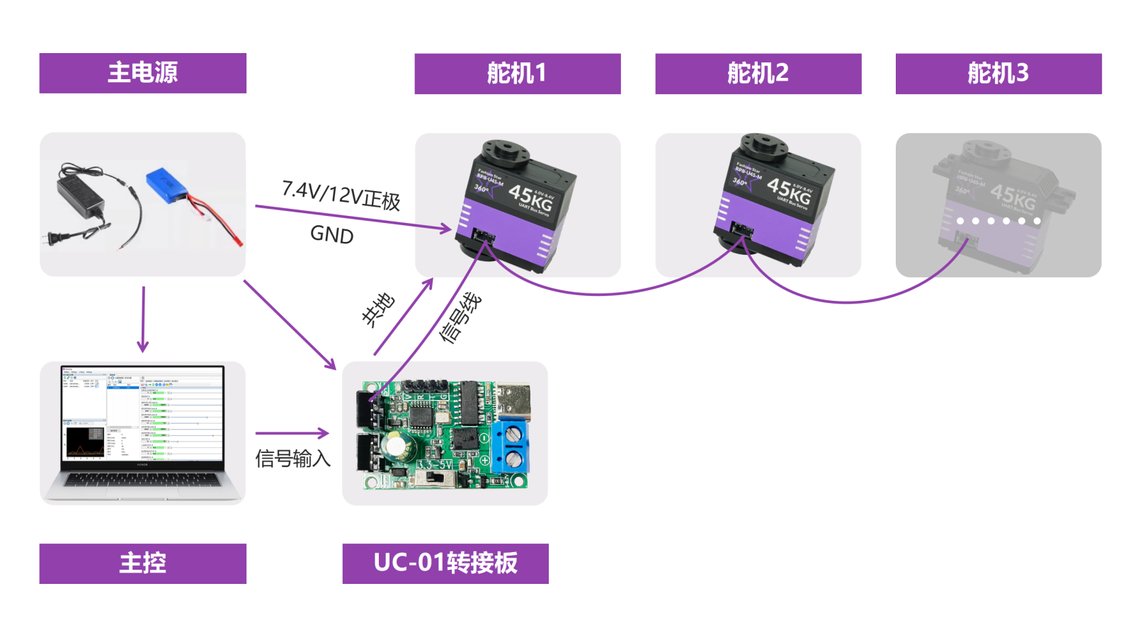
Use the UC01 adapter board to route both signal and power.
-
Advantage: wiring is simple and can be daisy-chained directly.
-
Limitation: each adapter board supports a maximum current of about 20 A. Plan the number of servo units according to the stall current of each model; use multiple adapter boards if the current limit is exceeded.
For example, if one 25 kg servo has a maximum stall current of 3 A, each adapter board should connect no more than 6 servo units.
2.2 Dedicated Power Wiring Scheme
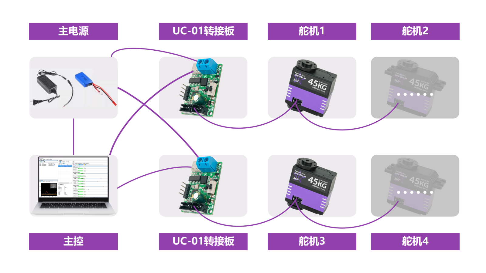
The adapter board only handles signal conversion from half-duplex to full-duplex, so only one adapter board is required. The power line is connected directly to the servo units.
- Power Daisy-Chain
The number of daisy-chain units depends on voltage drop across the wiring and connectors.
- Power Parallel Connection
If there are many servo units, voltage drop over cable length becomes significant. Do not daisy-chain the power line; instead, route the main power line separately and connect it in parallel to each servo.