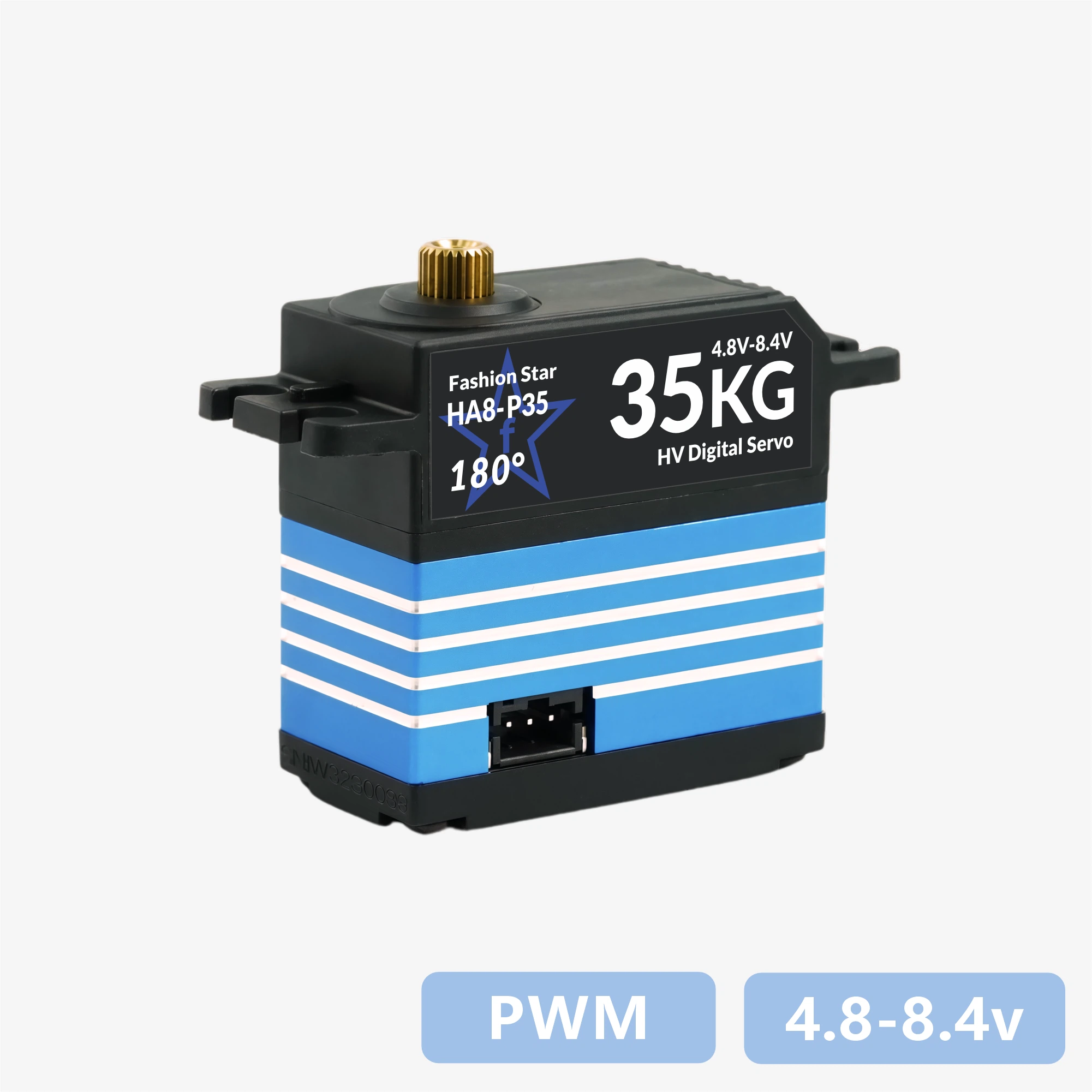
Datasheet - HA8-P35

1. Features
- Supports standard PWM control signals and is widely compatible with microcontrollers, servo controllers, and robot development platforms
- Built-in high-precision potentiometer position feedback enables smooth and stable closed-loop angle control
- Available in multiple physical travel options such as 180° / 270°, making it easier to match different mechanism travel requirements
- Supports a wide 6.0 V ~ 8.4 V input range, suitable for 2S LiPo batteries and common regulated power architectures
- Uses the industry-standard 25T output spline, compatible with common servo horns, metal arms, and structural accessories
- Uses a reinforced all-metal gear train with strong wear resistance and impact resistance
- Uses an aluminum CNC center case for better heat dissipation under high load
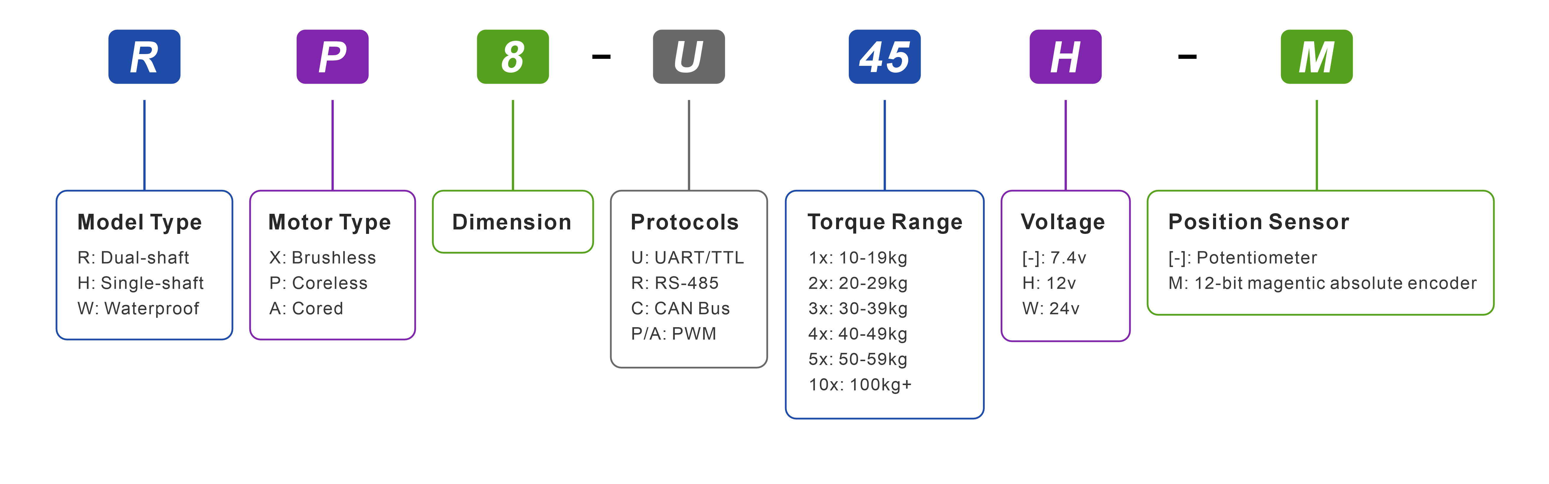
2. Model Naming
3. Specifications
3.1 Basic Specifications
| Parameter | Value |
|---|---|
| Operating Voltage | 6.0 ~ 8.4 V |
| Motor Type | Brushed Core Motor |
| Position Sensor | Potentiometer |
| Effective Angle | 180° (@500→2500μsec) |
| Rotation Direction | Counterclockwise(500→2500μsec) |
| Control Signal | PWM |
| PWM Period Range | 3 ~ 20 ms |
| Dead Band | 2 μs |
| Gear Ratio | 378:1 |
| Output Spline Spec | Aluminum / 25T |
| Output Spline Support | Dual Bearings |
| Connector Type | PH2.0 x 2 |
| Housing Material | Aluminum alloy center case / engineering plastic upper and lower covers |
| Dimensions | 40 x 40 x 20 mm |
| Weight | 52 g |
3.2 Performance Specifications
| Parameter | Value |
|---|---|
| Stall Torque | @8.4 V: 39 kg·cm @7.4 V: 35 kg·cm @6.0 V: 28 kg·cm |
| No-load Speed | @8.4 V: 0.183 sec / 60° @7.4 V: 0.208 sec / 60° @6.0 V: 0.256 sec / 60° |
| Stall Current | 3 A |
| No-load Current | 200 mA |
| Standby Current | 20 mA |
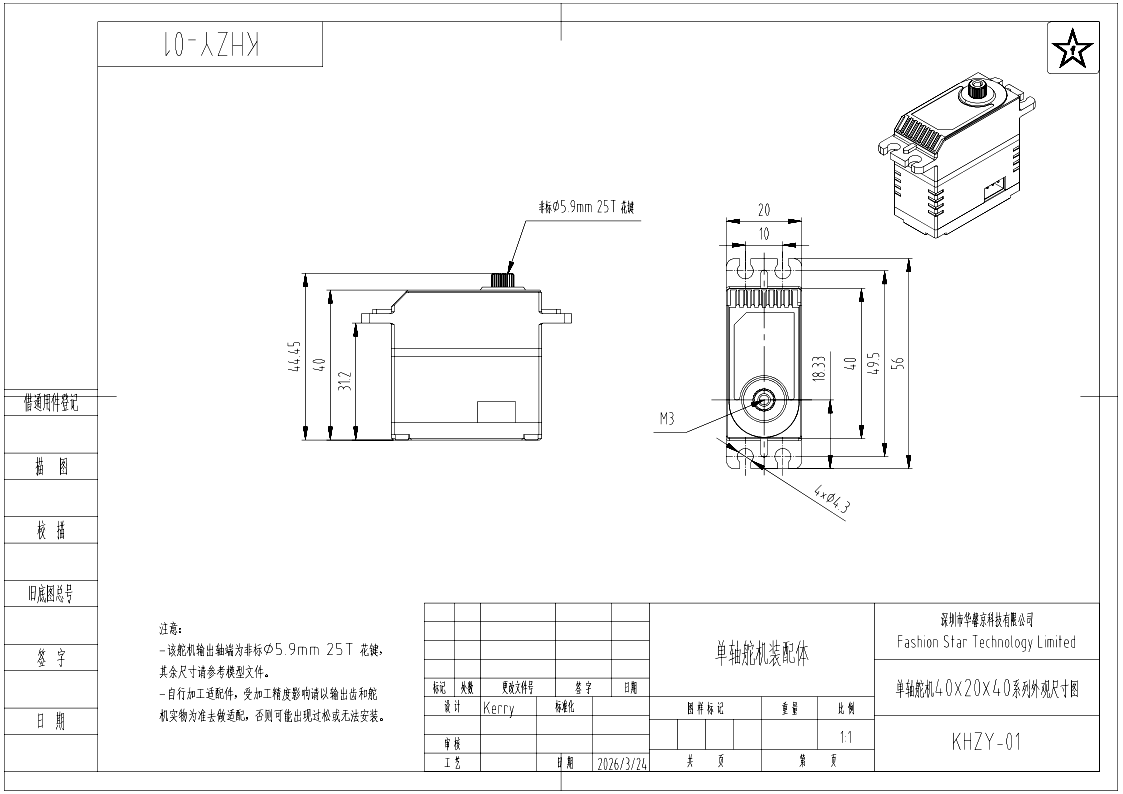
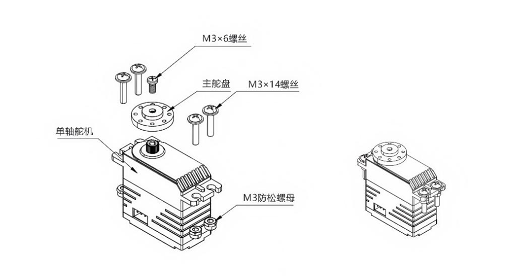
4. Dimensions & Installation
Downloads: PDF ~ STEP ~ DWG ~ More Part Drawings
Datasheet - HA8-U25-M / RA8-U25-M
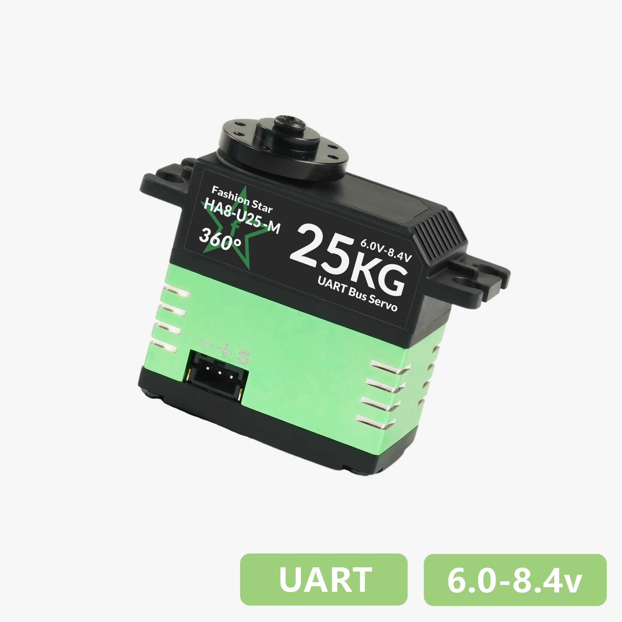
1. Features
- UART bidirectional communication, up to 1 Mbps, supports position and status feedback
- 12-bit absolute position encoder (4,096 counts resolution), supports arbitrary zero-point setting
- Supports a maximum multi-turn control range of ±368,640° (1,024 turns), with power-off position memory
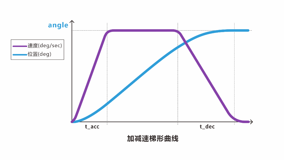
- Built-in trapezoidal acceleration/deceleration for smooth motion control
- Provides three stop modes: torque holding / torque release / damping control
- Integrated protections for temperature, voltage, stall, power, and current, with intelligent power limiting
- Includes a visual Master / PC Software for configuration, supports firmware upgrade
1. Features
- Designed with brushless motor / stainless-steel gear set / all-metal housing
- UART bidirectional communication, up to 1 Mbps, supports position and status feedback
- 12-bit absolute position encoder (4,096 counts resolution), supports arbitrary zero-point setting
- Supports a maximum multi-turn control range of ±368,640° (1,024 turns), with power-off position memory
- Built-in trapezoidal acceleration/deceleration for smooth motion control
- Provides three stop modes: torque holding / torque release / damping control
- Integrated protections for temperature, voltage, stall, power, and current, with intelligent power limiting
- Includes a visual Master / PC Software for configuration, supports firmware upgrade
1. Features
- Designed with brushless motor / stainless-steel gear set / all-metal housing
- RS485 bidirectional communication, up to 1 Mbps, supports position and status feedback
- 12-bit absolute position encoder (4,096 counts resolution), supports arbitrary zero-point setting
- Supports a maximum multi-turn control range of ±368,640° (1,024 turns), with power-off position memory
- Built-in trapezoidal acceleration/deceleration for smooth motion control
- Provides three stop modes: torque holding / torque release / damping control
- Integrated protections for temperature, voltage, stall, power, and current, with intelligent power limiting
- Includes a visual Master / PC Software for configuration, supports firmware upgrade
1. Features
- Designed with brushless motor / stainless-steel gear set
- UART bidirectional communication, up to 1 Mbps, supports position and status feedback
- 12-bit absolute position encoder (4,096 counts resolution), supports arbitrary zero-point setting
- Supports a maximum multi-turn control range of ±368,640° (1,024 turns), with power-off position memory
- Built-in trapezoidal acceleration/deceleration for smooth motion control
- Provides three stop modes: torque holding / torque release / damping control
- Integrated protections for temperature, voltage, stall, power, and current, with intelligent power limiting
- Includes a visual Master / PC Software for configuration, supports firmware upgrade
1. Features
- Supports standard PWM control signals and is widely compatible with microcontrollers, servo controllers, and robot development platforms
- Built-in high-precision potentiometer position feedback enables smooth and stable closed-loop angle control
- Available in multiple physical travel options such as 180° / 270°, making it easier to match different mechanism travel requirements
- Supports a wide 6.0 V ~ 8.4 V input range, suitable for 2S LiPo batteries and common regulated power architectures
- Uses the industry-standard 25T output spline, compatible with common servo horns, metal arms, and structural accessories
- Uses a reinforced all-metal gear train with strong wear resistance and impact resistance
- Uses an aluminum CNC center case for better heat dissipation under high load
1. Features
- Supports standard PWM control signals and is widely compatible with microcontrollers, servo controllers, and robot development platforms
- Equipped with a high-performance coreless motor for faster response and stronger torque output
- Built-in high-precision potentiometer position feedback enables smooth and stable closed-loop angle control
- Uses the industry-standard 25T output spline, compatible with common servo horns, metal arms, and structural accessories
- Built with a high-strength reinforced metal gear train that provides strong wear resistance and impact resistance
- Uses an aluminum CNC center case for better heat dissipation under high load
1. Features
- Supports standard PWM control signals and is widely compatible with microcontrollers, servo controllers, and robot development platforms
- Equipped with a high-performance brushless motor for faster response, higher efficiency, and longer service life
- Built-in high-precision magnetic encoder feedback enables smooth and stable closed-loop angle control
- Uses the industry-standard 25T output spline, compatible with common servo horns, metal arms, and structural accessories
- Built with a high-strength reinforced metal gear train that provides strong wear resistance and impact resistance
- Uses an aluminum CNC center case for better heat dissipation under high load
2. Model Naming
4. Dimensions & Installation
Downloads: PDF | STEP | DWG| More Part Drawings


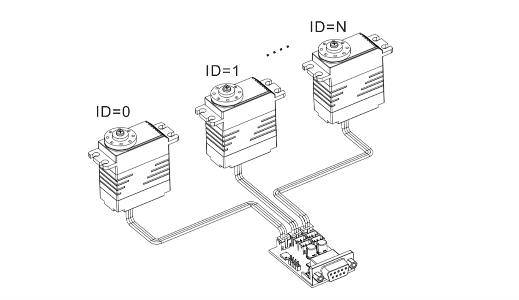
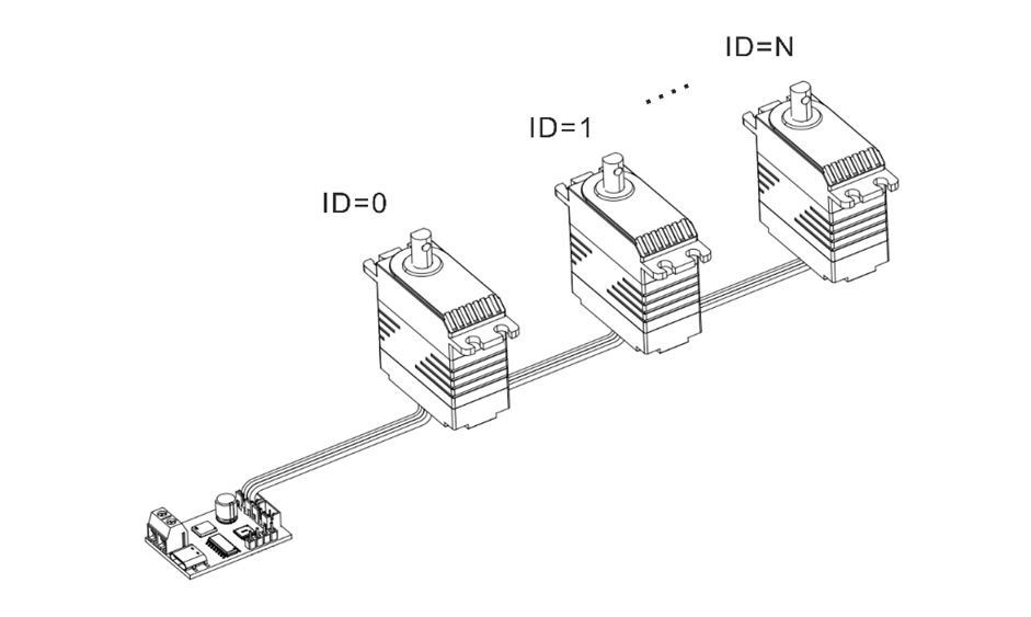
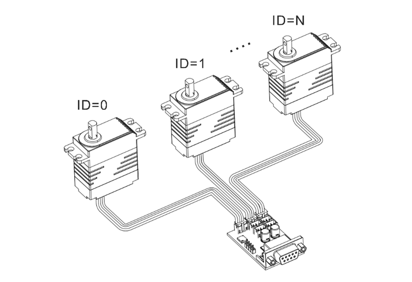
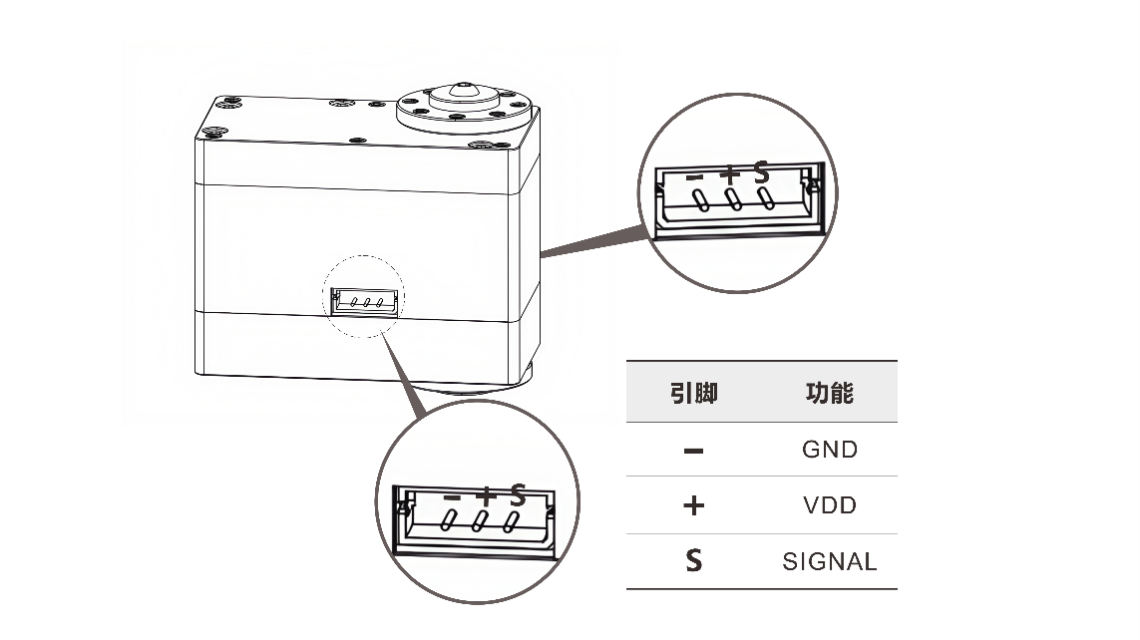
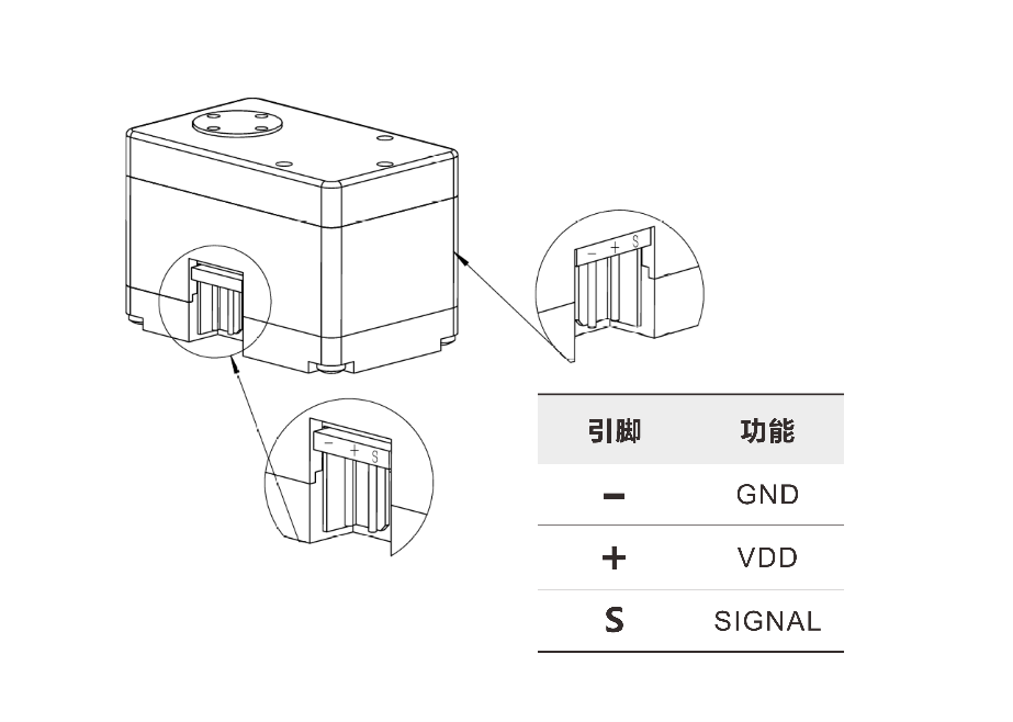
5. Interfaces & Wiring
5. Interfaces & Wiring
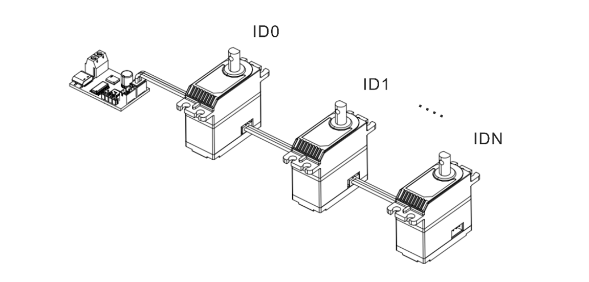
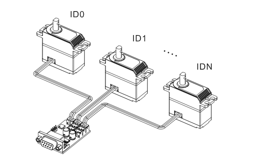
5. Interfaces & Wiring
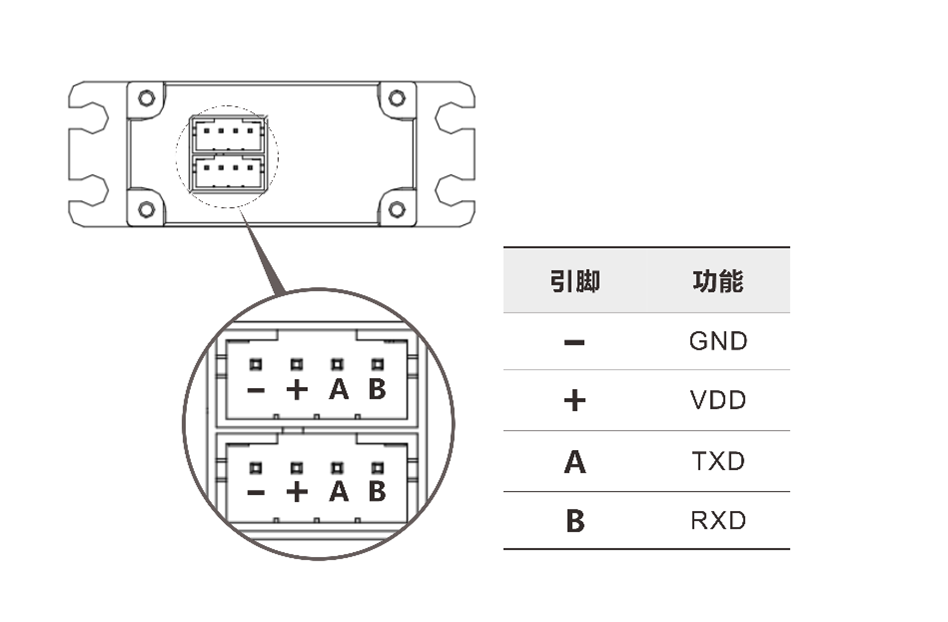
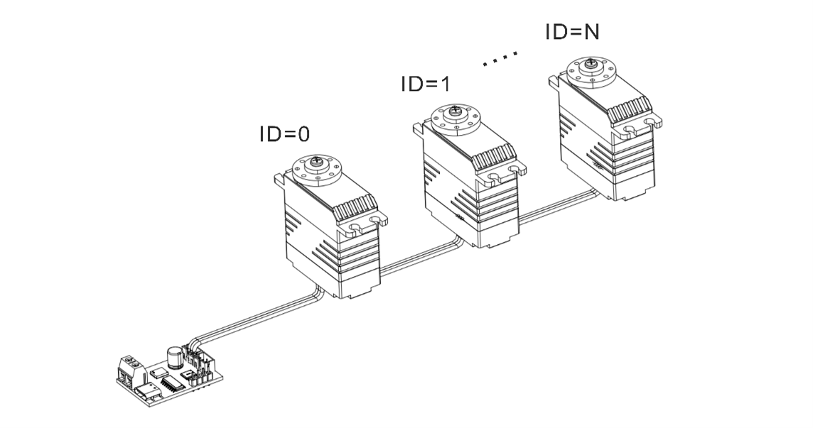
5. Interfaces & Wiring
5. Interfaces & Wiring
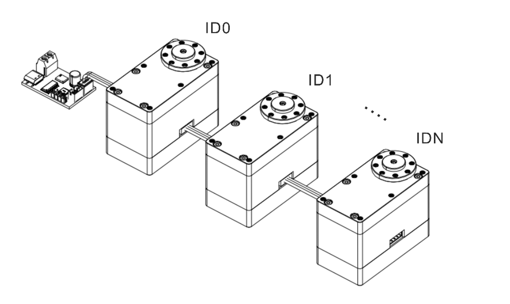
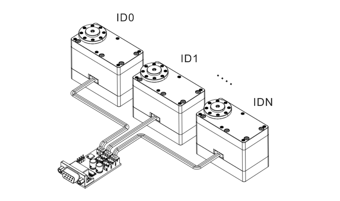
5. Interfaces & Wiring
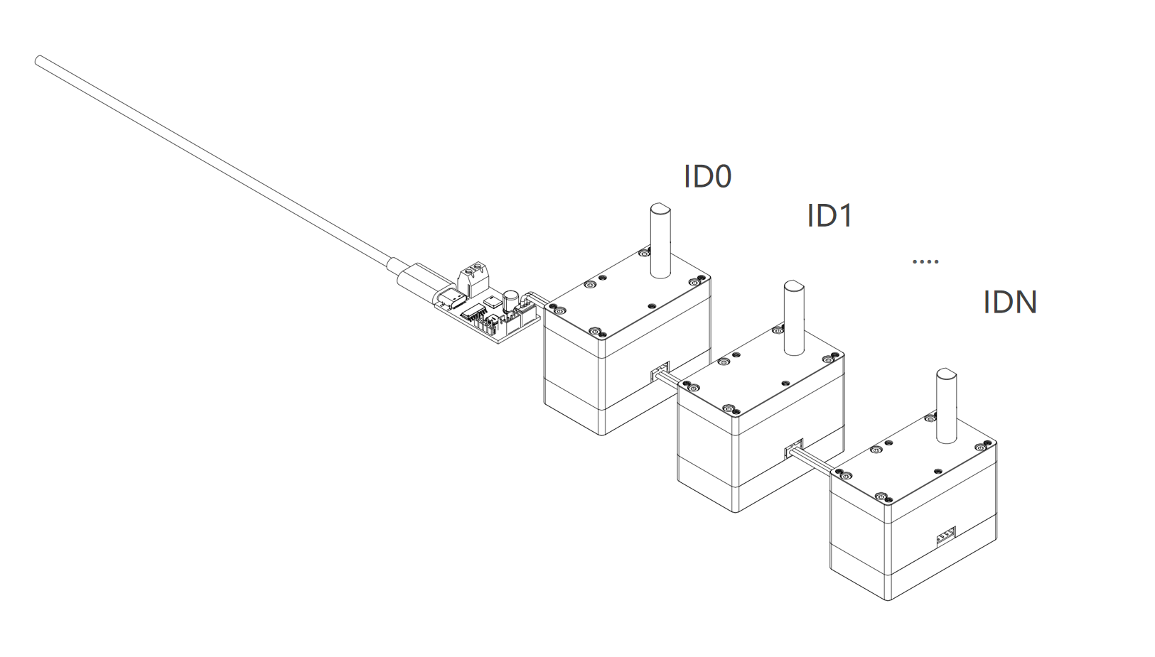
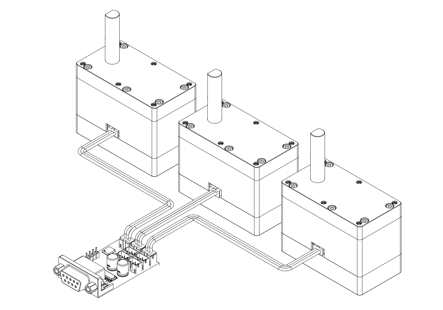
5. Interfaces & Wiring
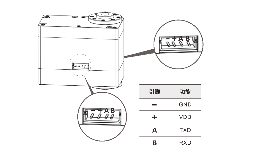
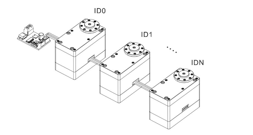
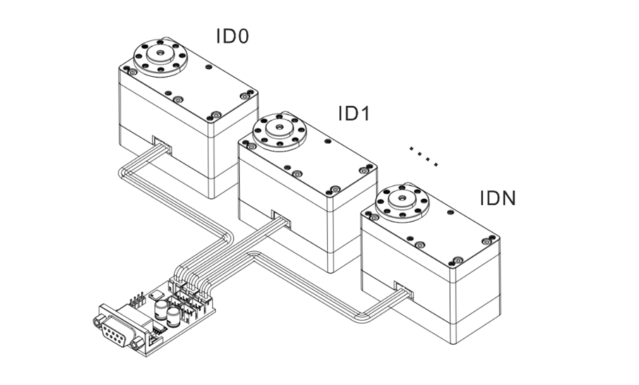
5. Interfaces & Wiring
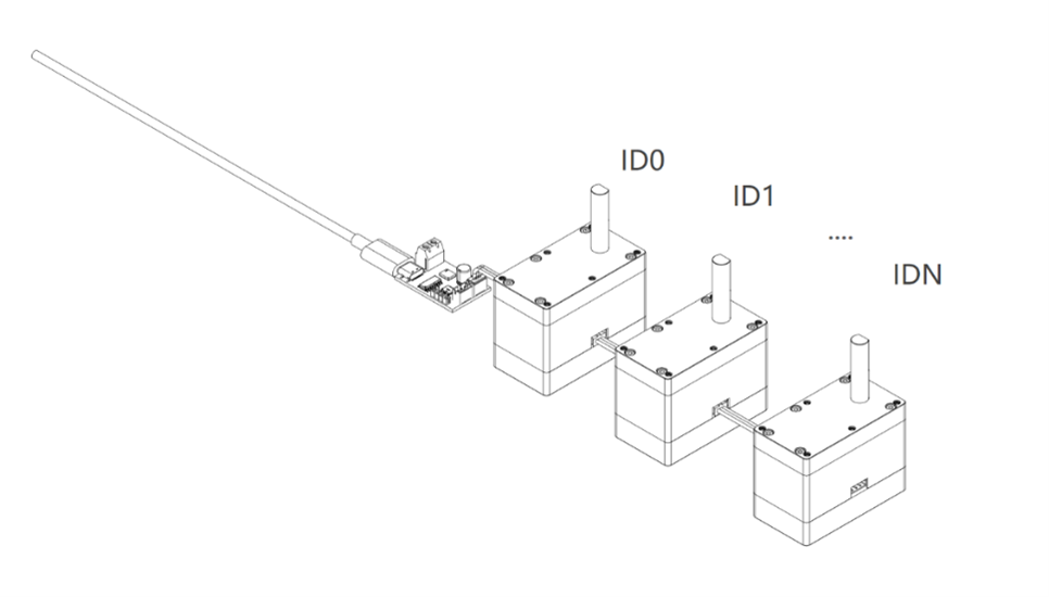
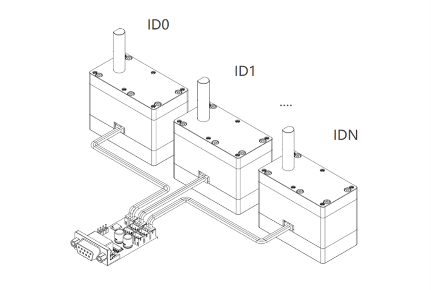
5. Interfaces & Wiring
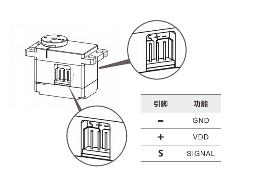
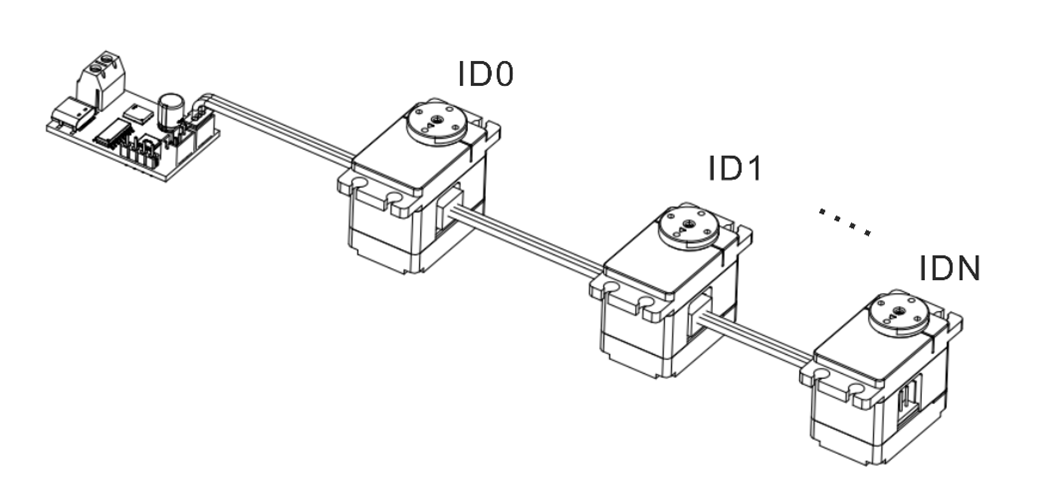
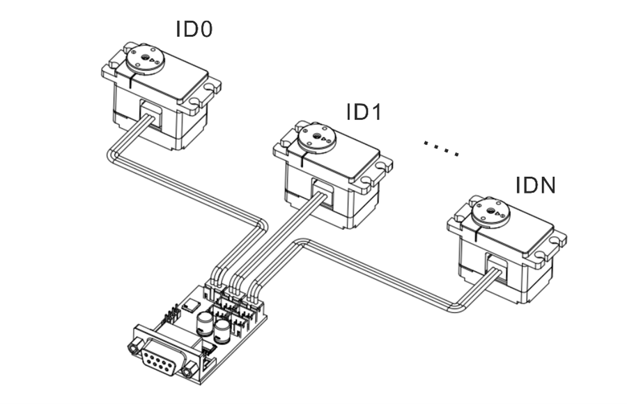
5. Interfaces & Wiring
6. Development Environment & SDK
Provides SDKs and example projects for mainstream control boards, programming languages, and robotics frameworks, enabling rapid validation, feature development, and system integration.
| Platform / Environment / Language | Supported Models / Content |
|---|---|
| Arduino | |
| ESP32 | |
| STM32 | |
| Raspberry Pi (Python) | |
| Programming Languages | |
| MATLAB |
|
| Robotics Frameworks |
6. PLC Applications / Development Environment & SDK
Provides SDKs and example projects for mainstream PLC platforms, control boards, and programming languages, enabling rapid validation, feature development, and system integration.
| Platform / Environment / Language | Supported Models / Content |
|---|---|
| Siemens (PLC) | |
| Mitsubishi (PLC) | |
| Inovance (PLC) | |
| Codesys(PLC) | |
| STM32 | |
| Programming Languages | |
| MATLAB |
|
7. Protection Features
Bus servos integrate multiple protections for temperature, voltage, stall, power, and current. The status flag bits can be used to determine which protection is currently triggered.
| Temperature Protection |
|---|
|
| Stall Protection |
|---|
|
| Power Protection |
|---|
|
| Voltage Protection |
|---|
|
| Current Protection |
|---|
|
Warning
- After voltage protection is triggered, you must power-cycle the servo before it can resume operation.
- Stall/power/current protections prevent overload damage. Setting thresholds too high may make protection ineffective.
- If temperature or current protection is triggered frequently, reduce the load or improve cooling and power supply.
Note
- The default temperature protection threshold is 70 °C.
- Default voltage protection ranges: 7.4 V version: 6.0-8.4 V / 12 V version: 9.0-12.6 V / 24 V version: 20.0-25.2 V.
- Current protection can be combined with stall and power protection. If the first two protections are not triggered by the Master / PC Software, current protection serves as the final hardware-level safeguard.
8. Commands & Protocol
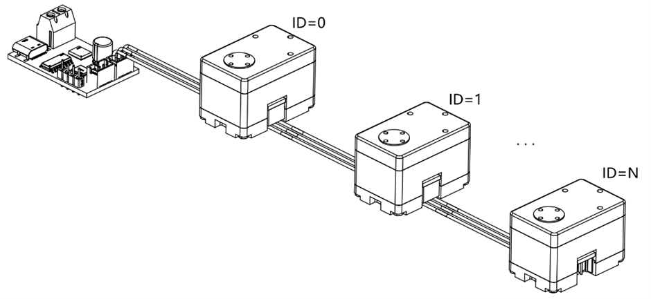
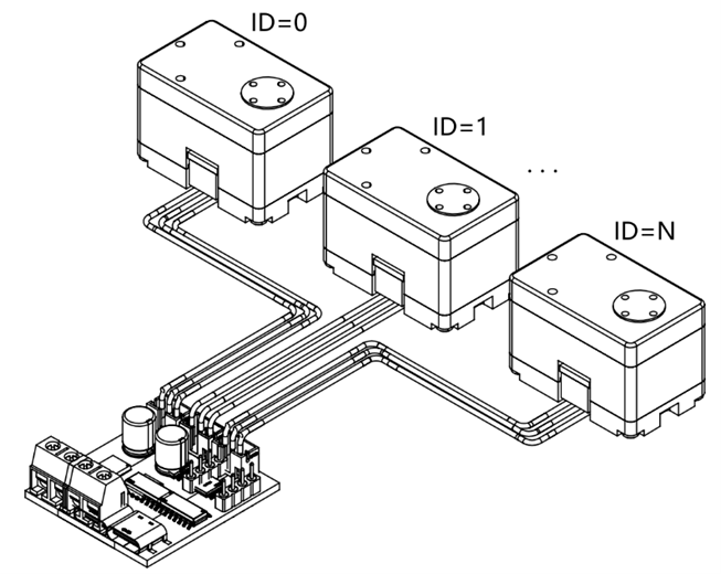
Bus servos use the UART/RS485 bus communication protocol. Based on half-duplex asynchronous serial communication and a command-response mechanism, it supports command delivery and status feedback between the controller and multiple servos. Each servo is identified on the bus by a unique ID (default ID = 0).
8.1 Control Commands
- Frame format: 8 data bits + 1 stop bit (no parity).
TxDandRxDcannot operate simultaneously. Only one device may transmit at any given time; all others must remain in receive-standby mode.- Recommended interval between consecutive commands: 5-10 ms.
| Command Name | Command ID | Response Packet Type |
|---|---|---|
| Communication Check | 01 (0x01) | Fixed |
| Basic Single-turn Position Control | 08 (0x08) | Configurable |
| Advanced Single-turn Position Control (Time-based) | 11 (0x0B) | Configurable |
| Advanced Single-turn Position Control (Speed-based) | 12 (0x0C) | Configurable |
| Read Single-turn Position | 10 (0x0A) | Fixed |
| Basic Multi-turn Position Control | 13 (0x0D) | Configurable |
| Advanced Multi-turn Position Control (Time-based) | 14 (0x0E) | Configurable |
| Advanced Multi-turn Position Control (Speed-based) | 15 (0x0F) | Configurable |
| Read Multi-turn Position | 16 (0x10) | Fixed |
| Reset Turns | 17 (0x11) | Configurable |
| Damping Control | 09 (0x09) | Configurable |
| Stop Command | 24 (0x18) | Configurable |
| Sync Command | 25 (0x19) | None |
| Async Write | 18 (0x12) | None |
| Async Execute | 19 (0x13) | None |
| Data Read | 03 (0x03) | Fixed |
| Data Monitor | 22 (0x16) | Fixed |
| Set Zero | 23 (0x17) | Configurable |
| Custom Parameters | 04 (0x04) | Configurable |
Note
By default, if a servo receives a new command while executing the current command, it immediately interrupts the current command and prioritizes the new one. The original command does not continue.
8.2 Command Packet
Command packet is the standard data structure used by the controller when sending control or query commands to the servo.
- header: fixed at
0x12 0x4C, used to identify the start of the command packet. - cmd_id: the control command associated with this packet.
-
length: the byte length of the following payload (
content), used to parse the packet. -
content: stores the control parameters defined by the command, such as servo ID, target angle, movement time, and power value.
- checksum: the sum of all bytes modulo 256, used to verify data integrity.

8.3 Response Packet
Response packet is the standard data structure used by the servo to return execution results and related data after receiving and validating a command packet.
Its overall structure matches the command packet, with differences only in the start marker and payload definition.
- header: fixed at
0x05 0x1C, used to identify the start of the response packet. - cmd_id: the control command associated with this packet.
-
length: the byte length of the following payload (
content), used to parse the packet. -
content: returns the execution result or related data defined by the command, such as current angle, voltage, temperature, firmware version, or readback parameters.
- checksum: the sum of all bytes modulo 256, used to verify data integrity.

9. Motion & Control Commands
9.1 Communication Check
Send the Communication Check command to the target ID and use the response packet to determine whether the servo is online.
| Command ID | Command Name | Description |
|---|---|---|
| 01 (0x01) | Communication Check | Response packet = online device ID |
9.2 Single-turn Position Control
- Supports time-based and speed-based control, and the current position can be obtained using the Read Single-turn Position command.
- Control range: ±180°, with a minimum control resolution of 0.1°.
| Command ID | Command Name | Parameters |
|---|---|---|
| 08 (0x08) | Basic Single-turn Position Control | Target angle, movement time, operating power |
| 11 (0x0B) | Advanced Single-turn Position Control (Time-based) | Target angle, movement time, acceleration time, deceleration time, operating power |
| 12 (0x0C) | Advanced Single-turn Position Control (Speed-based) | Target angle, speed, acceleration time, deceleration time, operating power |
| 10 (0x0A) | Read Single-turn Position | Response packet = current servo angle |
9.3 Multi-turn Position Control
- Supports time-based and speed-based control, and the current position can be obtained using the Read Multi-turn Position command.
- Control range: ±368,640° (±1,024 turns), with a minimum control resolution of 0.1°.
| Command ID | Command Name | Parameters |
|---|---|---|
| 13 (0x0D) | Basic Multi-turn Position Control | Target angle, movement time, operating power |
| 14 (0x0E) | Advanced Multi-turn Position Control (Time-based) | Target angle, movement time, acceleration time, deceleration time, operating power |
| 15 (0x0F) | Advanced Multi-turn Position Control (Speed-based) | Target angle, speed, acceleration time, deceleration time, operating power |
| 16 (0x10) | Read Multi-turn Position | Response packet = current servo angle |
9.4 Reset Turns / Power-off Position Memory
Reset Turns
- When the servo is in torque-release mode, you can use the Master / PC Software or the dedicated Reset Turns command to redefine the current absolute position as the current angle.
- After reset, the initial angle falls within the range of -180° to +180°.
| Command ID | Command Name | Description |
|---|---|---|
| 17 (0x11) | Reset Turns | - |
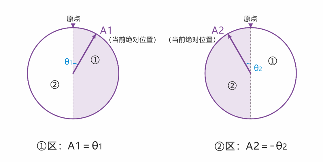
Note
As shown above, the current angle at point A1 is 6,880°, and after reset it becomes θ1. The current angle at point A2 is 6,800°, and after reset it becomes -θ2.
Power-off Position Memory
- After power-off, if the servo angle does not change, the current angle read after power-on remains unchanged. For example, if point A is 6,800° before power-off and the servo stays at point A while powered off, the angle read after power-on is still 6,800°.
- After power-off, if an external force causes the servo angle to change, the angle read after power-on falls within ±180° of the memorized angle.
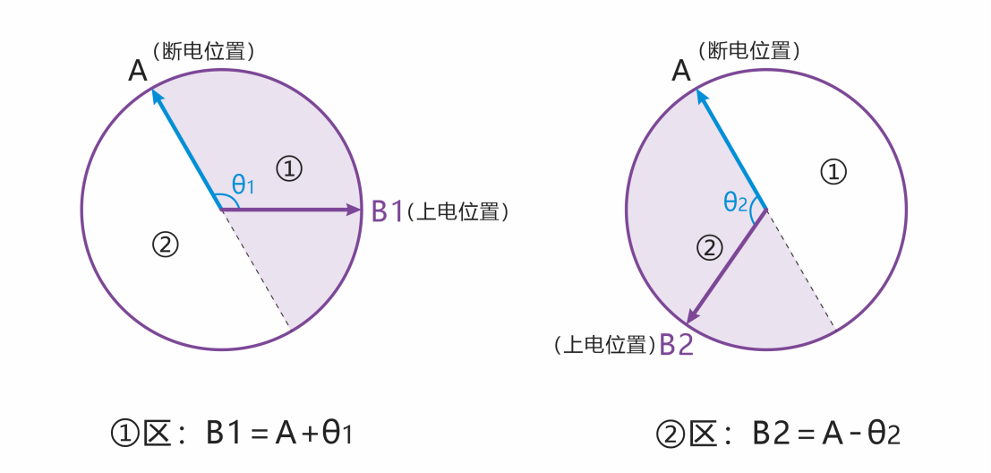
Note
As shown above, point A is 6,800° before power-off. If an external force rotates the servo during power-off and it finally stops at point B1, the angle read after power-on is 6,920°. If it stops at point B2, the angle read is 6,680°.
9.5 Damping Mode
Allows the servo to be moved to different angle positions by external force while maintaining a damping effect. The damping coefficient can be customized.
| Command ID | Command Name | Parameters |
|---|---|---|
| 09 (0x09) | Damping Control | Execution power (mW) |
9.6 Stop Command
- Choose the appropriate Stop Command type for different motion-control needs. The available types are listed below.
- Stop Command can also be used to restore normal operation after stall protection is triggered.
- When the servo is in torque-release mode, sending the "Torque Hold" command rebuilds holding torque from the current position.
| Command ID | Command Name | Description |
|---|---|---|
| 24 (0x18) | Torque Release | Stops motion and releases holding torque. |
| 24 (0x18) | Torque Hold | Stops motion and maintains holding torque, or rebuilds holding torque if it was previously released. |
| 24 (0x18) | Damping Hold | Stops motion and enters damping mode, allowing the angle to be adjusted by external force. |
9.7 Sync Command
- A single command can contain control data for multiple servos, making it suitable for coordinated multi-servo actions.
- Each servo matches the parameters in the command by its unique ID and only parses and responds to the control data associated with that ID.
- After all servos receive the command, they start executing their respective actions at the same time to achieve synchronized motion.
| Command ID | Command Name | Description |
|---|---|---|
| 25 (0x19) | Sync Command | - |
9.8 Async Commands
- Async commands consist of two parts: Async Write and Async Execute.
- Buffered motion commands remain stored until they are rewritten or power is removed. They are not overwritten or cleared by other commands.
- After an async command is triggered, the related parameters are cleared automatically and are no longer retained.
| Command ID | Command Name | Description |
|---|---|---|
| 18 (0x12) | Async Write | Writes the target motion command into the servo register buffer without executing it immediately. |
| 19 (0x13) | Async Execute | Triggers the buffered async motion commands together so multiple servos execute in sync. |
9.9 Status Read / Data Monitor
Used to read servo status and key parameters for debugging, inspection, and real-time display in the Master / PC Software.
| Command ID | Command Name | Description |
|---|---|---|
| 03 (0x03) | Data Read | Reads a single servo status parameter or configuration parameter and returns the corresponding value. |
| 22 (0x16) | Data Monitor | Returns the complete status set, including voltage, current, power, temperature, status flags, angle, and turn count. |
9.10 Set Zero
Sets the current servo position as the zero point. This is commonly used for post-assembly zero calibration and as a unified motion reference for control algorithms.
| Command ID | Command Name | Parameters |
|---|---|---|
| 23 (0x17) | Set Zero | Servo ID / reset = 0 |
10. More Resources
-
Used to connect the bus servo to a PC or other controller for communication debugging and data exchange.
-
Provides ID configuration, real-time control for multiple operating modes, parameter configuration, status monitoring, and firmware upgrade tools.
-
Covers engineering practice topics such as communication protocols, control logic, parameter configuration, and troubleshooting.