UART / RS-485 Bus Servo SDK Development Manual (STM32F103)
| 版本 | GitHub | 开发资源包 |
|---|---|---|
| v1.2026.0305 |  |
点击下载 |
This SDK wraps the low-level C API based on the bus servo UART / RS-485 Communication Protocol, helping developers quickly implement precise control, status readback, and multi-axis synchronous control for all supported bus servo models on the STM32F103 platform.
Quick Start
After the basic development environment and hardware wiring are ready, use the entries below to jump directly to the corresponding function examples.
Each example provides complete code that can be copied, compiled, and run directly for quick verification and debugging.
- ▶️ Check Whether the Servo Is Online
- ▶️ Control a Single Servo for Complex Motion
- ▶️ Control Multiple Servo with Serial Commands
- ▶️ Deadband Evaluation and Autonomous Motion Closed Loop
- ▶️ Multi-Turn Large-Angle Motion Control
- ▶️ Continuous Rotation of the Servo
- ▶️ Timed Rotation of the Servo
- ▶️ Fixed-Turn Rotation of the Servo
- ▶️ Experience Damping Feel
- ▶️ Damping Mode and Motion Trajectory Capture
- ▶️ Automatically Switch to Damping After Motion Completes
- ▶️ System-Level Millisecond Synchronous Coordination
- ▶️ Delayed Trigger for Asynchronous Commands
- ▶️ Full Monitoring of Servo Sensor Data
- ▶️ Read Servo Parameters
=== Part 1: Environment Setup ===
1. Resource Preparation
Before writing code, make sure the following software and hardware development resources are ready:
1.1 Development Tools and Driver Software
-
Includes the complete low-level driver library and test examples, ready for project import and function verification.
-
PC Configuration Software Configuration Software
Used to graphically test servo parameters and motions.
-
The C/C++ integrated development environment recommended for STM32, used to compile and download firmware.
-
Serial Port Assistant (ATK-XCOM v3.0) — Extraction code:
ktsy.Used to view MCU log output and communication status data.
-
The USB-to-TTL driver commonly used by adapter boards and configuration modules.
-
Provides recognition, firmware flashing, and configuration support for the ST-Link downloader.
Click the Development Resource Package at the top of this page to download all resources in one package.
1.2 Hardware Preparation
Option 1 (Strongly Recommended for Beginners)
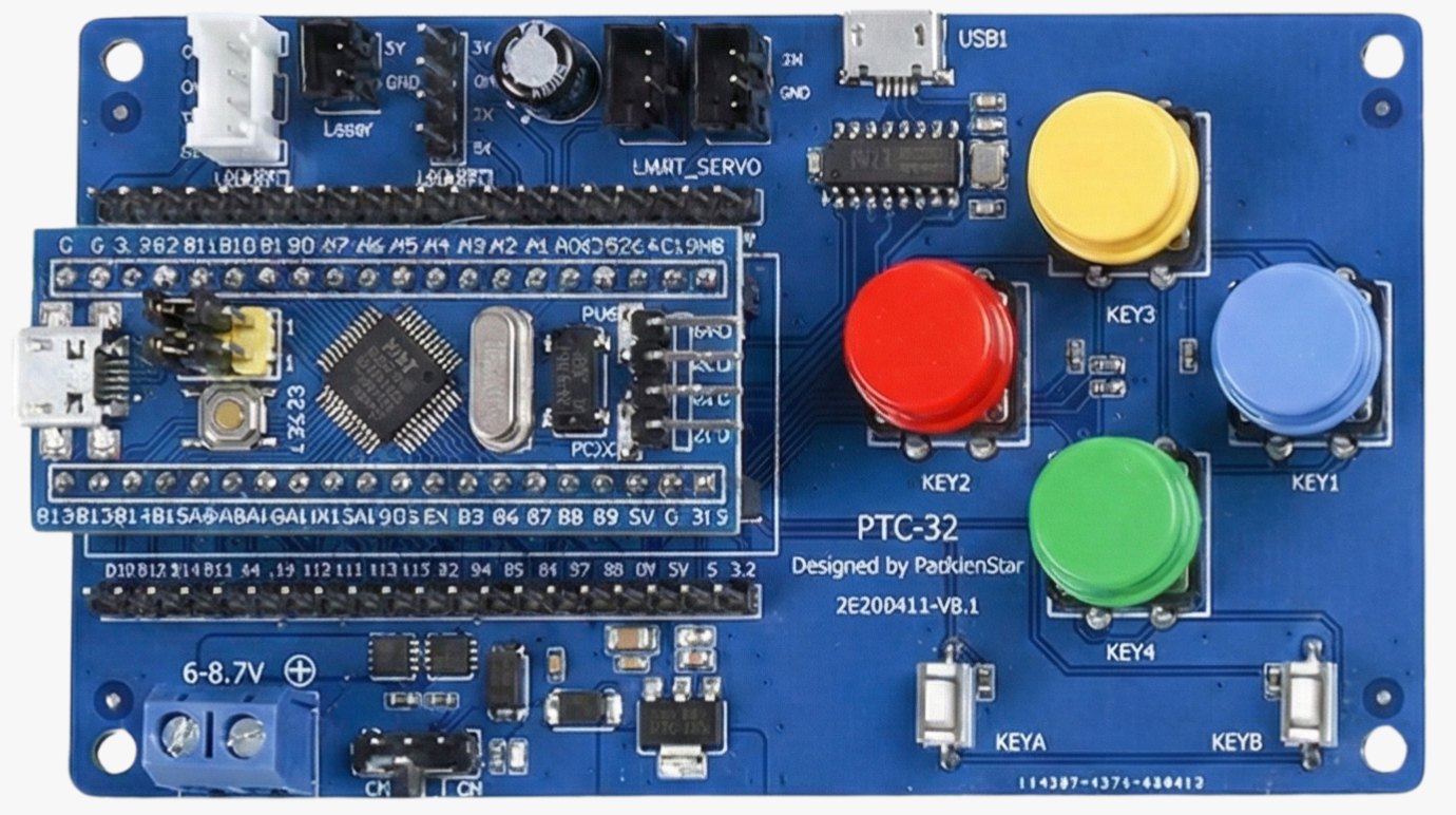
Use the STM32 all-in-one controller board (PTC-32). This controller integrates the functions of STM32F103C8T6 and the servo adapter board UC-01 at the hardware level. It removes complex wiring, works out of the box, and greatly reduces early-stage hardware troubleshooting time.
Option 2 (Advanced Expansion)
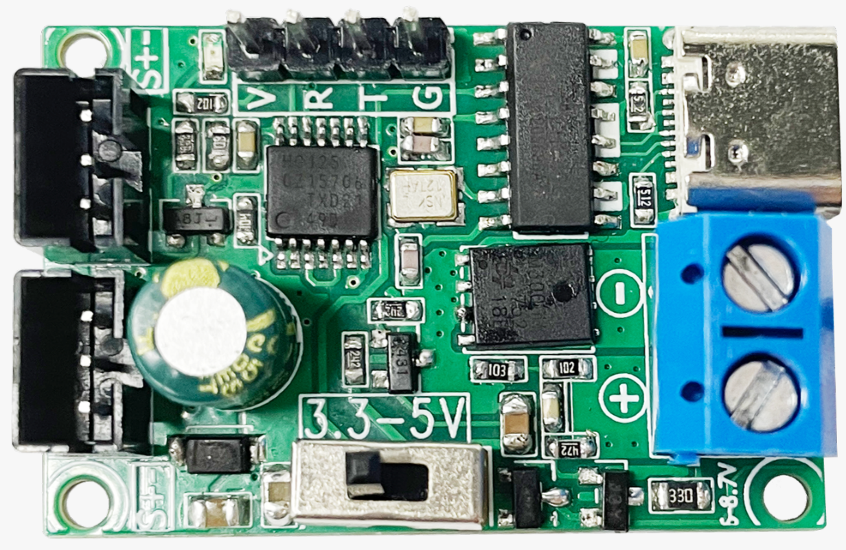
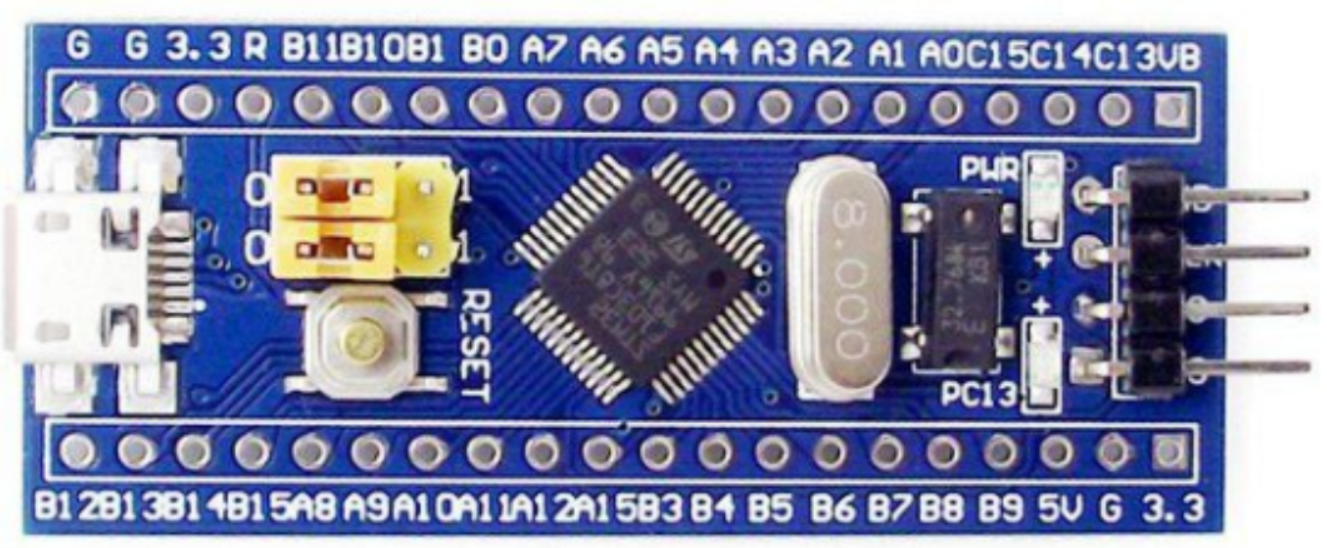
Core board + UC-01 adapter board combination Suitable for developers who already have a controller board or need to integrate servo into a more complex robot system. This option provides high flexibility.
2. Hardware Wiring Instructions
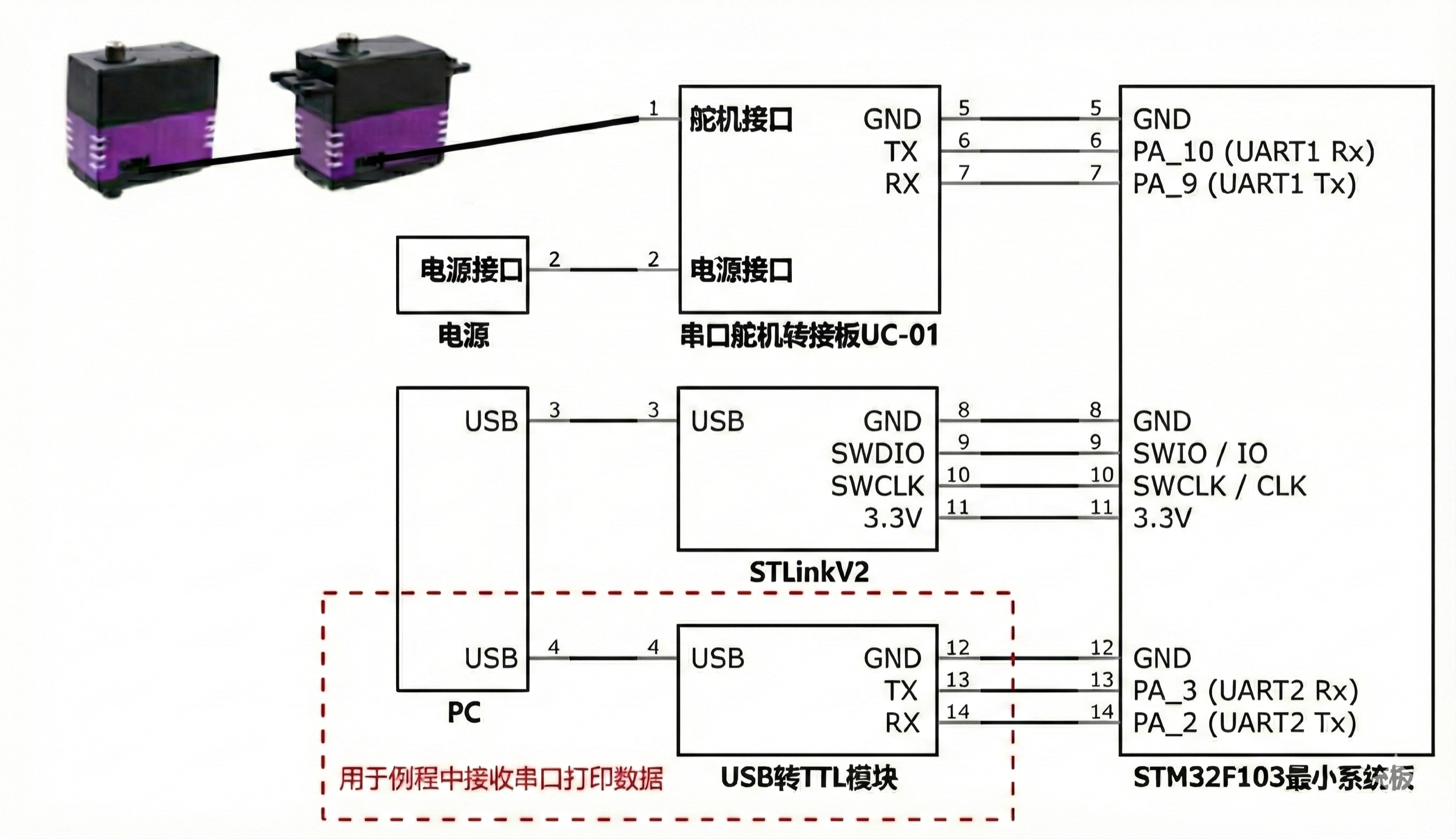
2.1 Serial Port Resource Allocation Convention
In the provided SDK examples, the hardware serial port (UART) resources of STM32F103 are assigned as follows:
UART1: Control communication channel. Connects to the Bus Servo adapter board, used to send control commands and receive Servo feedback.UART2: Log output channel (optional). Connects to a USB-to-TTL module, used to printprintfConfiguration information to the PC.UART3: Reserved and not used by default.
2.2 Physical Wiring Topology
Firmware Download Wiring (ST-Link v2 <-> STM32)
Used to flash the compiled firmware.
| ST-Link V2 Pin | STM32 Core Board Pin |
|---|---|
| SWDIO | SWIO / IO |
| SWCLK | SWCLK / CLK |
| GND | GND |
| 3.3V | 3V3 |
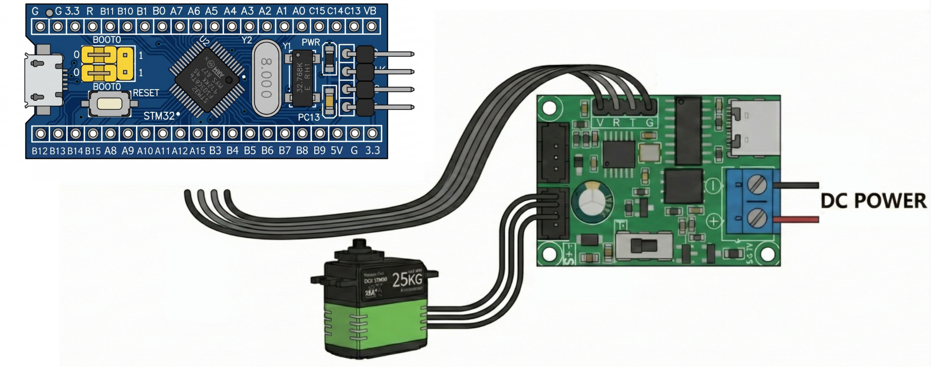
Control Communication Wiring (STM32 UART1 <-> Servo Adapter Board)
If you use the STM32 all-in-one controller board (PTC-32), skip this step. This step applies only to Option 2: core board + UC-01 adapter board.
| STM32F103 GPIO | Bus Servo Adapter Board UC01 | Wiring Description |
|---|---|---|
| PA_9 (UART1 Tx) | Rx | MCU sends control commands |
| PA_10 (UART1 Rx) | Tx | MCU receives servo feedback data |
| 5V | 5V | Logic-level reference, depending on adapter board power supply |
| GND | GND | Common ground, required |
Log Configuration Wiring (STM32 UART2 <-> USB-to-TTL) - Optional
| STM32F103 GPIO | USB-to-TTL Module (External) | Wiring Description |
|---|---|---|
| PA_2 (UART2 Tx) | Rx | MCU outputs printf logs |
| PA_3 (UART2 Rx) | Tx | Receives PC-side configuration commands, reserved |
| GND | GND | Common ground, required |
Overall Topology Diagram
3. Project Configuration and Build Structure
3.1 Project Import and Keil5 Configuration
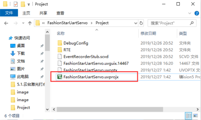
After extracting the downloaded SDK source package fashionstar-uart-servo-stm32f103-master, enter the corresponding example directory. The steps below use the communication check example as the reference:
- 1. Open the project: double-click
/FashionStarUartServo/Project/FashionStarUartServo.uvprojxto launch Keil5.
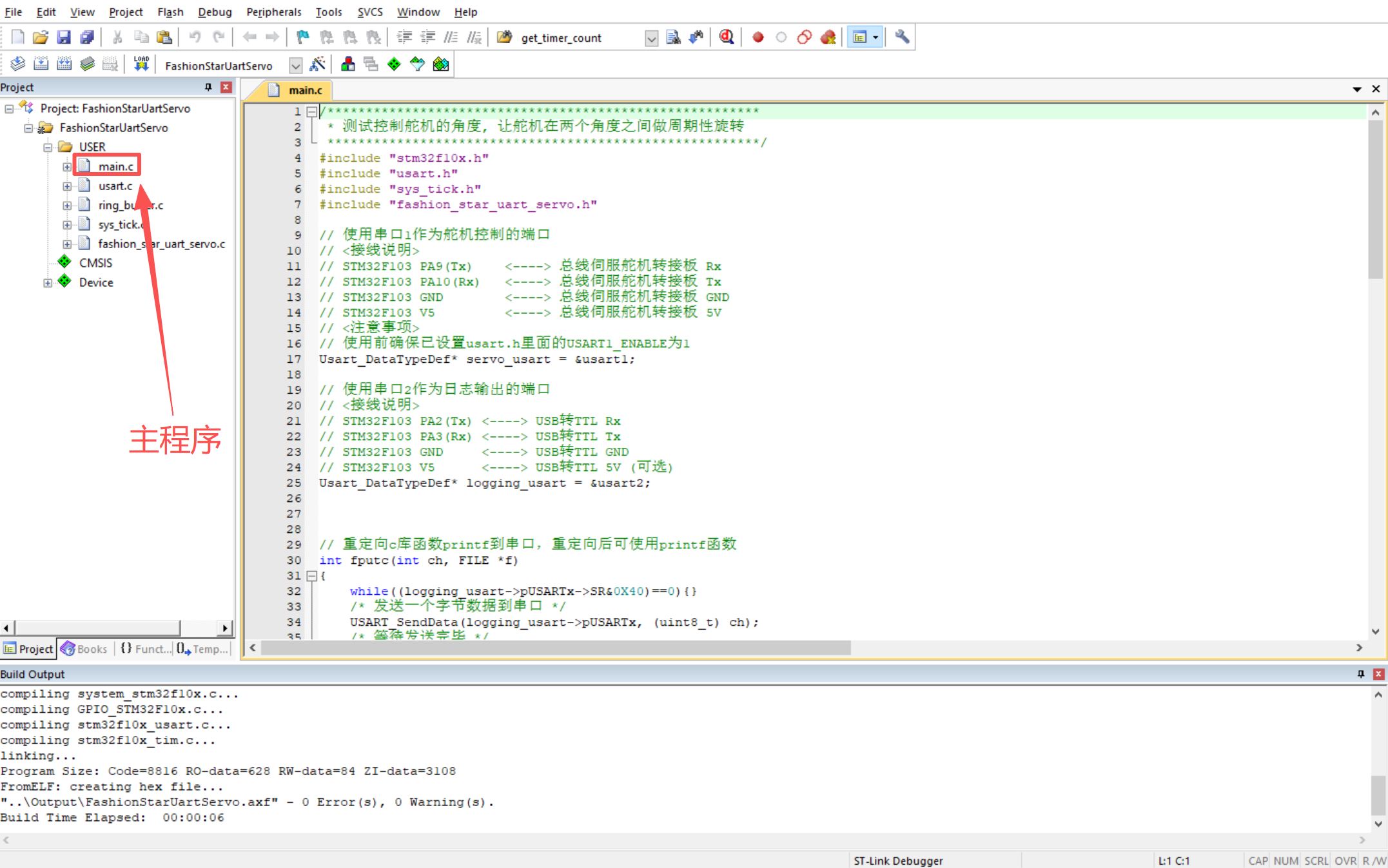
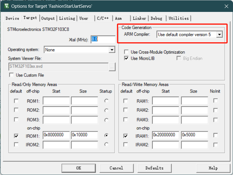
- 2. Configure the compiler: make sure the project uses Use default compiler version 5 (ARM Compiler 5) for compatibility.
- 3. Configure the downloader: in the
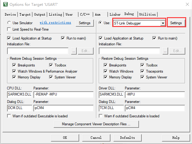
Options for Target->Debugtab, select the Debugger you are using. The standard configuration in this manual is ST-Link Debugger.
3.2 Build and Firmware Download
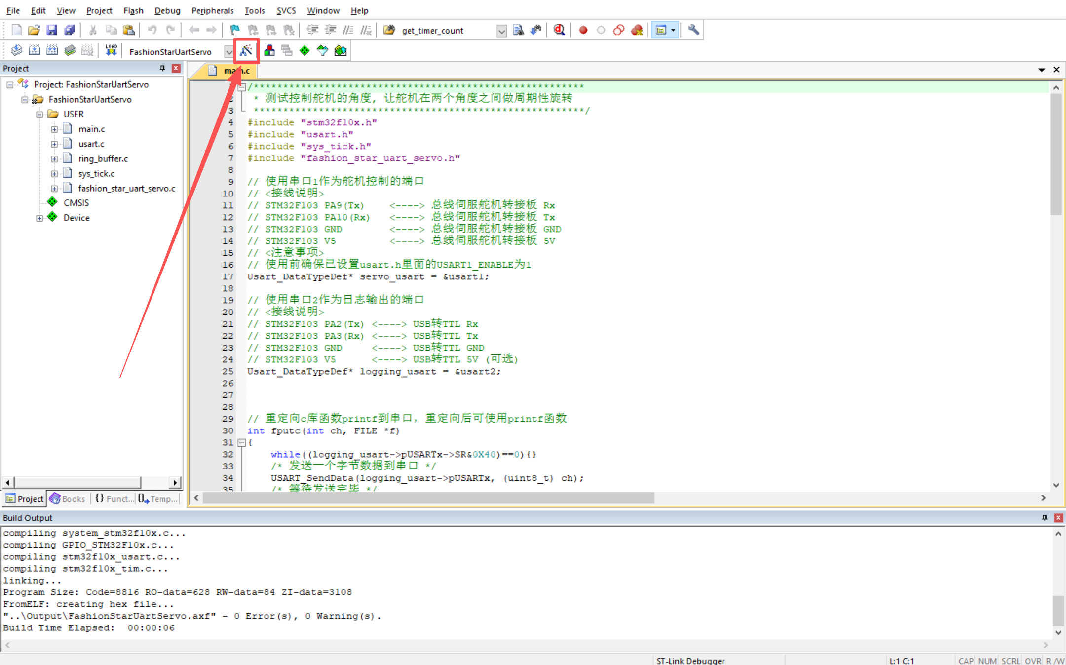
- 1. Click the
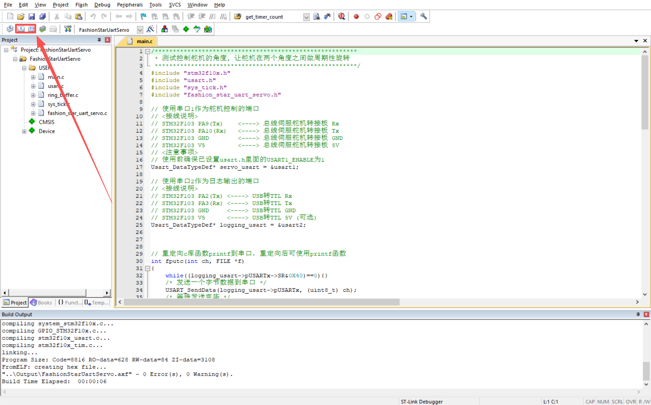
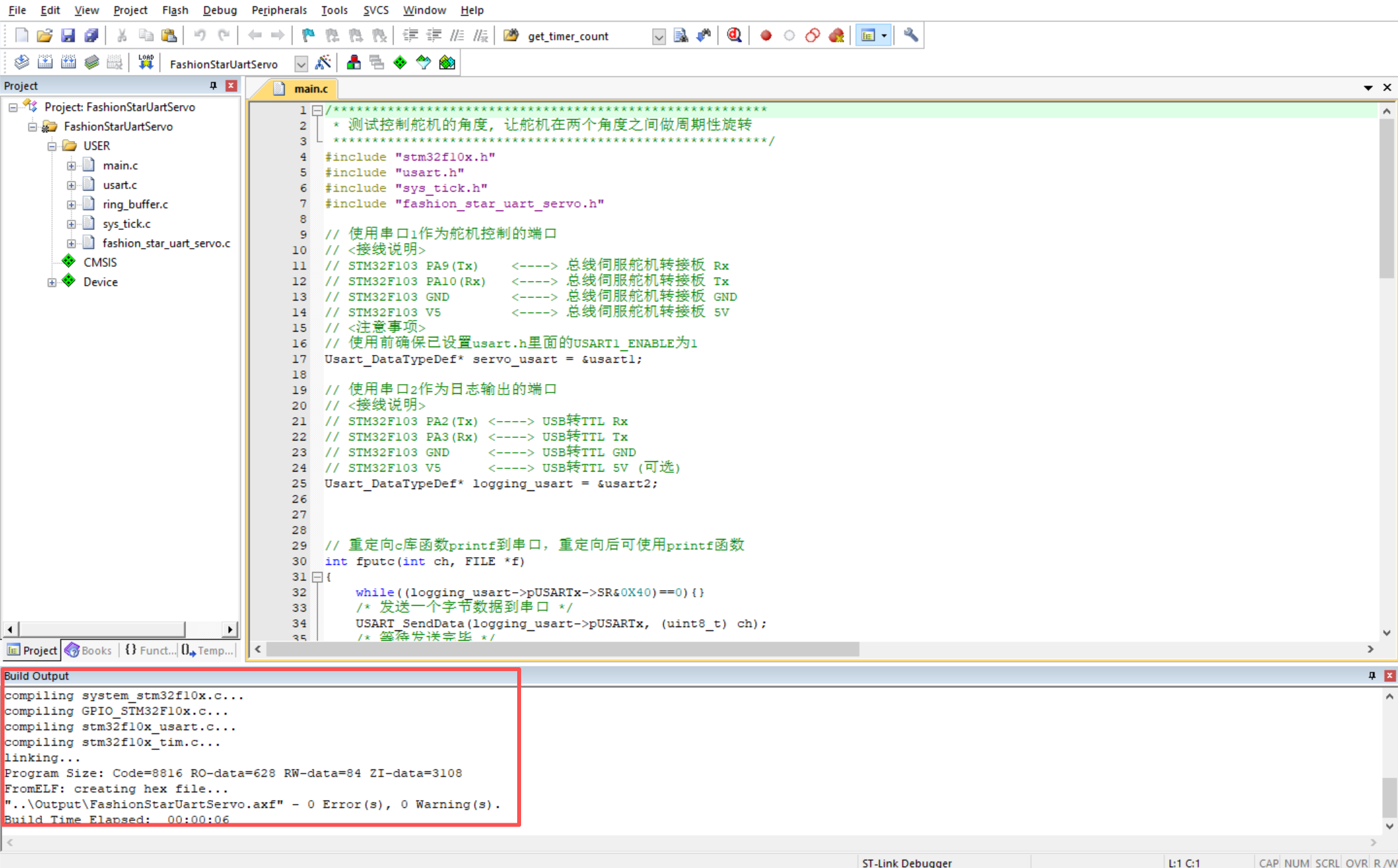
Buildbutton at the top of Keil to build the project. Check theBuild Outputwindow below and confirm that it shows0 Error(s), 0 Warning(s).
- 2. Plug ST-Link into a USB port on the computer, then click
Downloadto flash the firmware to the STM32 chip.
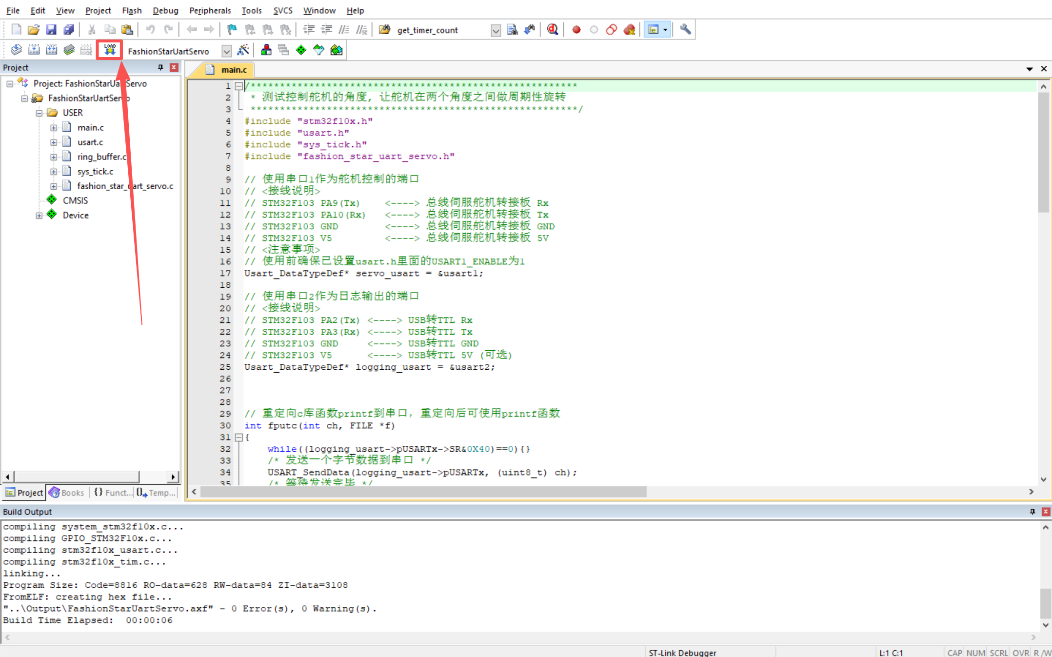
- 3. After flashing is complete, press the Reset button on the STM32 core board. The program will start running.
3.3 SDK Project Directory Tree
For easier secondary development, review the module structure under the SDK User folder:
├── fashion_star_uart_servo    // 核心:FashionStar 舵机通信协议封装层 API
│   ├── fashion_star_uart_servo.c
│   └── fashion_star_uart_servo.h
├── main.c                     // 业务层:用户主程序入口
├── ring_buffer                // 底层组件:C语言实现的环形缓冲队列(处理串口字节流)
│   ├── README.md
│   ├── ring_buffer.c
│   └── ring_buffer.h
├── stm32f10x_conf.h
├── sys_tick                   // 底层组件:系统时间管理(封装延时与倒计时函数)
│   ├── sys_tick.c
│   └── sys_tick.h
└── usart                      // 底层组件:串口通信驱动(提供宏定义快捷开关 UART1/2/3)
    ├── README.md
    ├── usart.c
    └── usart.h
=== Part 2: servo Function APIs and Core Examples ===
4. Communication Check (Ping)
Before performing complex motion control, verify that the physical link and communication protocol are working properly. Sending a Ping command checks whether the servo with a specific ID on the bus is online. If the servo is online, it immediately returns a response packet containing its basic status.
Function Prototype
FSUS_STATUS FSUS_Ping(
    Usart_DataTypeDef *usart,
    uint8_t servo_id
);
Parameter Description
usart: pointer to the Serial Port data object corresponding to Servo control, such as&usart1.servo_id: ID of the Servo to check.
Return Value
- Returns the status code
FSUS_STATUS. - Returns
0(FSUS_STATUS_SUCCESS) if the request succeeds. A non-zero value indicates communication failure. - For the complete error codes, refer to
fashion_star_uart_servo.h.
Function Call Example
statusCode = FSUS_Ping(servoUsart, servoId);
▶️ Check Whether the Servo Is Online
Logic Description:
- Continuously sends communication check commands to servo ID 0.
- Prints the online status of the servo in the UART2 log serial port according to the response status code.
Complete Example Code
/********************************************************
 * 测试通信检测指令,测试舵机是否在线
 ********************************************************/
#include "stm32f10x.h"
#include "usart.h"
#include "sys_tick.h"
#include "fashion_star_uart_servo.h"

// 使用串口1作为舵机控制的端口
// <接线说明>
// STM32F103 PA9(Tx)  <----> 总线伺服舵机转接板 Rx
// STM32F103 PA10(Rx) <----> 总线伺服舵机转接板 Tx
// STM32F103 GND      <----> 总线伺服舵机转接板 GND
// STM32F103 V5       <----> 总线伺服舵机转接板 5V
// <注意事项>
// 使用前确保已设置usart.h里面的USART1_ENABLE为1
// 设置完成之后, 将下行取消注释
Usart_DataTypeDef* servoUsart = &usart1;

// 使用串口2作为日志输出的端口
// <接线说明>
// STM32F103 PA2(Tx) <----> USB转TTL Rx
// STM32F103 PA3(Rx) <----> USB转TTL Tx
// STM32F103 GND     <----> USB转TTL GND
// STM32F103 V5      <----> USB转TTL 5V (可选)
// <注意事项>
// 使用前确保已设置usart.h里面的USART2_ENABLE为1
Usart_DataTypeDef* loggingUsart = &usart2;

// 重定向c库函数printf到串口,重定向后可使用printf函数
int fputc(int ch, FILE *f)
{
    while((loggingUsart->pUSARTx->SR&0X40)==0){}
    /* 发送一个字节数据到串口 */
    USART_SendData(loggingUsart->pUSARTx, (uint8_t) ch);
    /* 等待发送完毕 */
    // while (USART_GetFlagStatus(USART1, USART_FLAG_TC) != SET);
    return (ch);
}

// 连接在转接板上的总线伺服舵机ID号
uint8_t servoId = 0;
// 发送Ping请求的状态码
FSUS_STATUS statusCode;

int main (void)
{
    // 嘀嗒定时器初始化
    SysTick_Init();
    // 串口初始化
    Usart_Init();

    while (1)
    {
        printf("\r\n");
        // Ping一下舵机
        printf("[INFO]ping servo %d \r\n", servoId);
        statusCode = FSUS_Ping(servoUsart, servoId);
        printf("[INFO]status code %d \r\n", statusCode);

        // 根据状态码做不同的处理
        if (statusCode == FSUS_STATUS_SUCCESS){
            printf("[INFO]ping success, servo %d echo \r\n", servoId);
        }else{
            printf("[ERROR]ping fail, servo %d not online \r\n", servoId);
        }
        // 等待1000ms
        SysTick_DelayMs(1000);
    }
}
5. Single-Turn Angle Control
- Command overwrite: servo follows the latest-command-first rule. When angle control commands are sent continuously, a new command immediately overwrites the previous one. Add a delay between consecutive motions, or poll the current angle to determine whether the motion has completed.
- bus protection: when sending commands continuously to the same servo, keep the command interval above 10 ms.
- Power holding: if
power = 0or the configured value is greater than the system power holding value, the servo uses the configured power holding value by default. This can be modified through PC configuration software. - Physical limits: the actual time required to reach the target position depends on the maximum physical speed of the servo model and the current external load.
Simple Single-Turn Angle Control
This is the most basic point-to-point control method. It moves the servo to the specified angle within the specified cycle time.
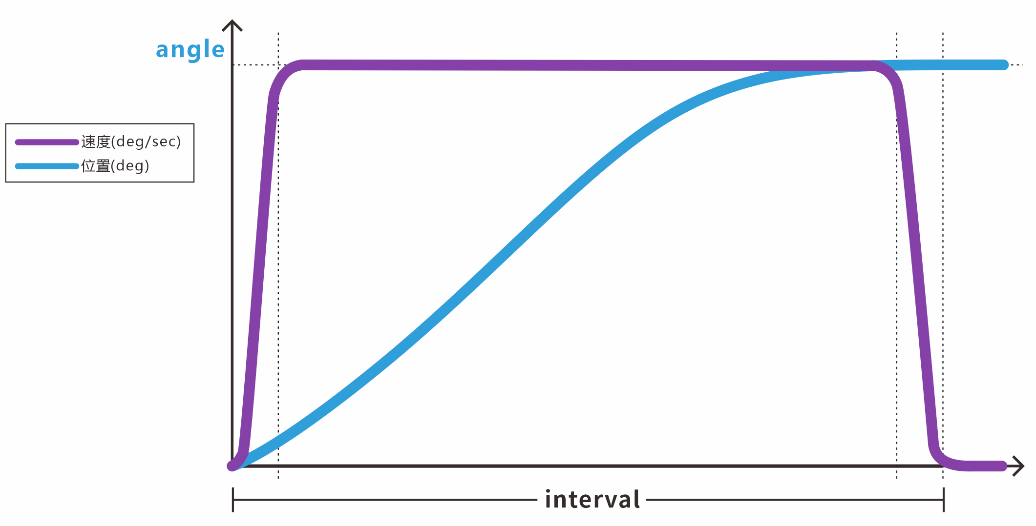
Function Prototype
FSUS_STATUS FSUS_SetServoAngle(
    Usart_DataTypeDef *usart,
    uint8_t servo_id,
    float angle,
    uint16_t interval,
    uint16_t power,
    uint8_t wait
);
Parameter Description
usart: Serial Port data objectUsart_DataTypeDefcorresponding to Servo control.servo_id: target Servo ID.angle: target absolute angle. The minimum unit is 0.1°, and the valid range is[-180.0, 180.0].interval: expected motion run time (ms).power: maximum power limit (mV) for this motion. The default is0.wait: API blocking mode.0means non-blocking, where the API returns after the command is sent.1means blocking wait, where the API blocks until the Servo rotates into position.
Function Call Example
// 舵机控制相关的参数
uint8_t servoId = 0;  // 舵机的ID号
float angle = 0;// 舵机的目标角度  舵机角度在-180度到180度之间, 最小单位0.1°
uint16_t interval = 2000; // 运行时间ms  可以尝试修改设置更小的运行时间,例如500ms
uint16_t power = 0; // 舵机执行功率 单位mV 默认为0
uint8_t wait = 0; //  API是否为阻塞式,0:不等待 1:等待舵机旋转到特定的位置;

FSUS_SetServoAngle(servoUsart, servoId, angle, interval, power, wait);
Advanced Single-Turn Angle Control (Time-Based)
This mode adds trapezoidal speed planning to the basic control method. By specifying the acceleration time and deceleration time, it effectively reduces mechanical jitter and current impact during start and stop.
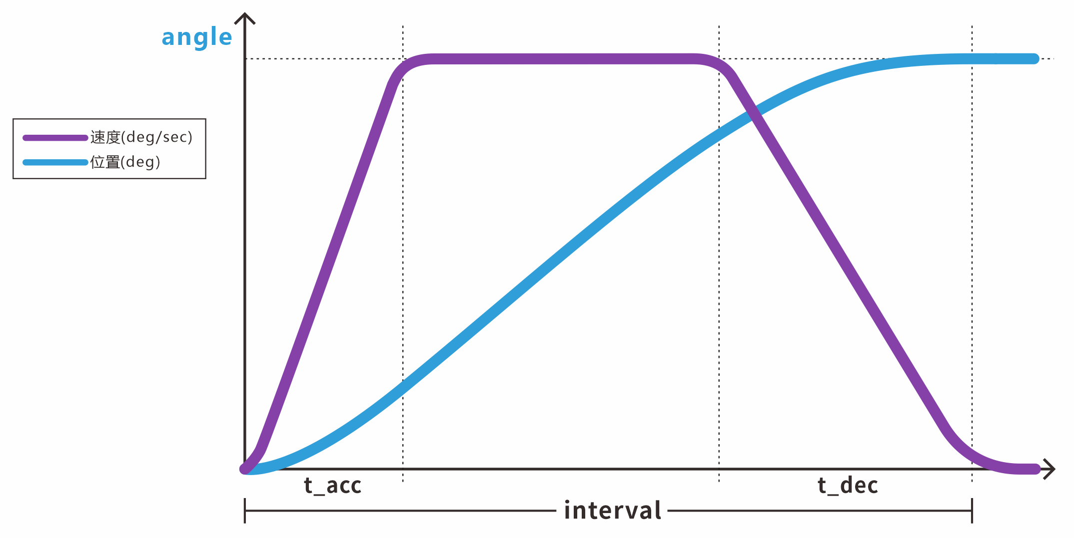
Function Prototype
FSUS_STATUS FSUS_SetServoAngleByInterval(
    Usart_DataTypeDef *usart,
    uint8_t servo_id,
    float angle,
    uint16_t interval,
    uint16_t t_acc,
    uint16_t t_dec,
    uint16_t power,
    uint8_t wait
);
Parameter Description
interval: total run time (ms), which must satisfyinterval > t_acc + t_dec.t_acc: time required to accelerate from rest to the constant-speed stage (ms), with a minimum value of> 20.t_dec: time required to decelerate from constant speed to stop (ms), with a minimum value of> 20. (Other parameters are the same as above.)
Function Call Example
//// 舵机控制相关的参数
// 舵机的ID号
uint8_t servoId = 0;
// 舵机的目标角度
// 舵机角度在-180度到180度之间, 最小单位0.1°
float angle = 0;
// 运行时间ms
// 可以尝试修改设置更小的运行时间,例如500ms
uint16_t interval = 2000;
// 加速时间
uint16_t t_acc = 100;
// 减速时间
uint16_t t_dec = 150;
// 舵机执行功率 单位mV 默认为0
uint16_t power = 0;
 //  API是否为阻塞式,0:不等待 1:等待舵机旋转到特定的位置;
uint8_t wait = 0;

FSUS_SetServoAngleByInterval(servo_usart, servo_id, angle, interval, t_acc, t_dec, power, wait);
Advanced Single-Turn Angle Control (Speed-Based)
This mode is suitable for applications that need the servo to move to the target point at a specific constant physical speed.
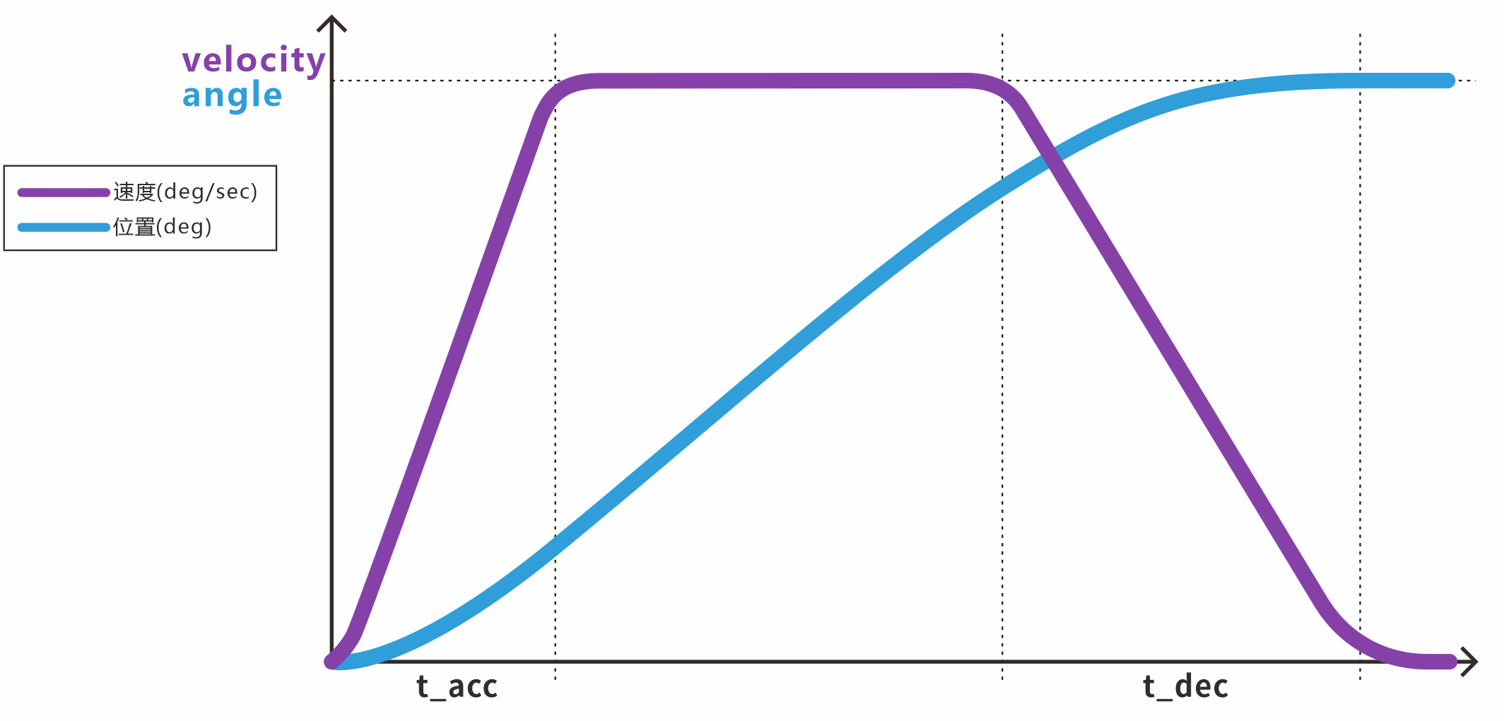
Function Prototype
FSUS_STATUS FSUS_SetServoAngleByVelocity(
    Usart_DataTypeDef *usart,
    uint8_t servo_id,
    float angle,
    float velocity,
    uint16_t t_acc,
    uint16_t t_dec,
    uint16_t power,
    uint8_t wait
);
Parameter Description
velocity: target cruising speed in °/s. The valid range is[1, 750]. (Other parameters are the same as above.)
Function Call Example
//// 舵机控制相关的参数
// 舵机的ID号
uint8_t servoId = 0;
// 舵机的目标角度
// 舵机角度在-180度到180度之间, 最小单位0.1°
float angle = 0;
// 目标转速
float velocity;
// 加速时间
uint16_t t_acc = 100;
// 减速时间
uint16_t t_dec = 150;
// 舵机执行功率 单位mV 默认为0
uint16_t power = 0;
 //  API是否为阻塞式,0:不等待 1:等待舵机旋转到特定的位置;
uint8_t wait = 0;

FSUS_SetServoAngleByVelocity(servo_usart, servo_id, angle, velocity, t_acc, t_dec, power, wait);
Read Current Single-Turn Angle
Reads the absolute angle of the current physical position of the servo.
Function Prototype
// 查询单个舵机的角度信息 angle 单位度
FSUS_STATUS FSUS_QueryServoAngle(
    Usart_DataTypeDef *usart,
    uint8_t servo_id,
    float *angle
);
Function Call Example
uint8_t servoId = 0;    // 舵机的ID号
float curAngle = 0;     // 舵机当前所在的角度
FSUS_QueryServoAngle(servoUsart, servoId, &curAngle); // 读取一下舵机的角度
//curAngle = 当前单圈角度
▶️ Control a Single Servo for Complex Motion
Logic Description:
- Demonstrates the three single-turn control APIs above.
- The servo moves back and forth in different control modes. After each motion completes, the callback query API prints the reached angle in real time, making it easier to compare the behavior of different speed planning modes.
Complete Example Code:
/********************************************************
 * 测试控制舵机的角度, 让舵机在两个角度之间做周期性旋转
 ********************************************************/
#include "stm32f10x.h"
#include "usart.h"
#include "sys_tick.h"
#include "fashion_star_uart_servo.h"

// 使用串口1作为舵机控制的端口
// <接线说明>
// STM32F103 PA9(Tx)    <----> 总线伺服舵机转接板 Rx
// STM32F103 PA10(Rx)   <----> 总线伺服舵机转接板 Tx
// STM32F103 GND        <----> 总线伺服舵机转接板 GND
// STM32F103 V5         <----> 总线伺服舵机转接板 5V
// <注意事项>
// 使用前确保已设置usart.h里面的USART1_ENABLE为1
Usart_DataTypeDef* servo_usart = &usart1;

// 使用串口2作为日志输出的端口
// <接线说明>
// STM32F103 PA2(Tx) <----> USB转TTL Rx
// STM32F103 PA3(Rx) <----> USB转TTL Tx
// STM32F103 GND     <----> USB转TTL GND
// STM32F103 V5      <----> USB转TTL 5V (可选)
Usart_DataTypeDef* logging_usart = &usart2;


// 重定向c库函数printf到串口,重定向后可使用printf函数
int fputc(int ch, FILE *f)
{
    while((logging_usart->pUSARTx->SR&0X40)==0){}
    /* 发送一个字节数据到串口 */
    USART_SendData(logging_usart->pUSARTx, (uint8_t) ch);
    /* 等待发送完毕 */
    // while (USART_GetFlagStatus(USART1, USART_FLAG_TC) != SET);
    return (ch);
}


//// 舵机控制相关的参数
// 舵机的ID号
uint8_t servo_id = 0;
// 舵机的目标角度
// 舵机角度在-180度到180度之间, 最小单位0.1°
float angle = 0;
// 运行时间ms
// 可以尝试修改设置更小的运行时间,例如500ms
uint16_t interval;
// 目标转速
float velocity;
// 加速时间
uint16_t t_acc;
// 减速时间
uint16_t t_dec;
// 舵机执行功率 单位mV 默认为0
uint16_t power = 0;
// 设置舵机角度的时候, 是否为阻塞式
// 0:不等待 1:等待舵机旋转到特定的位置;
uint8_t wait = 1;
// 读取的角度
float angle_read;

int main (void)
{
    // 嘀嗒定时器初始化
    SysTick_Init();
    // 串口初始化
    Usart_Init();

    while (1){
        printf("GOTO: 135.0f\r\n");
        // 简易角度控制 + 当前角度查询
        angle = 135.0;
        interval = 2000;
        FSUS_SetServoAngle(servo_usart, servo_id, angle, interval, power, wait);
        FSUS_QueryServoAngle(servo_usart, servo_id, &angle_read);
        printf("Cur Angle: %.1f\r\n", angle_read);

        // 等待2s
        SysTick_DelayMs(2000);

        // 带加减速的角度控制(指定周期) + 当前角度查询
        printf("GOTO+Interval: 0.0f\r\n");
        angle = 0.0f;
        interval = 1000;
        t_acc = 100;
        t_dec = 150;
        FSUS_SetServoAngleByInterval(servo_usart, servo_id, angle, interval, t_acc, t_dec, power, wait);
        FSUS_QueryServoAngle(servo_usart, servo_id, &angle_read);
        printf("Cur Angle: %.1f\r\n", angle_read);

        // 等待2s
        SysTick_DelayMs(2000);

        // 带加减速的角度控制(指定转速) + 当前角度查询
        printf("GOTO+Velocity: -135.0f\r\n");
        angle = -135.0f;
        velocity = 200.0f;
        t_acc = 100;
        t_dec = 150;
        FSUS_SetServoAngleByVelocity(servo_usart, servo_id, angle, velocity, t_acc, t_dec, power, wait);
        FSUS_QueryServoAngle(servo_usart, servo_id, &angle_read);
        printf("Cur Angle: %.1f\r\n", angle_read);
  }
}
Reference Terminal Output Log: a small steady-state error can be observed in the actual reached angle
GOTO: 135.0f
Cur Angle: 134.7
GOTO+Interval: 0.0f
Cur Angle: 0.3
GOTO+Velocity: -135.0f
Cur Angle: -134.6
▶️ Control Multiple Servo with Serial Commands
Logic Description:
- Uses non-blocking mode (
wait=0) to continuously send control commands to the bus. - Works with delays in the MCU main loop to implement basic coordination between servo ID 0 and ID 1.
If strict synchronization is required for multiple servo, use synchronous commands.
Complete Example Code:
#include "stm32f10x.h"
#include "usart.h"
#include "sys_tick.h"
#include "fashion_star_uart_servo.h"

// 使用串口1作为舵机控制的端口
// <接线说明>
// STM32F103 PA9(Tx)    <----> 总线伺服舵机转接板 Rx
// STM32F103 PA10(Rx)   <----> 总线伺服舵机转接板 Tx
// STM32F103 GND        <----> 总线伺服舵机转接板 GND
// STM32F103 V5         <----> 总线伺服舵机转接板 5V
// <注意事项>
// 使用前确保已设置usart.h里面的USART1_ENABLE为1
// 设置完成之后, 将下行取消注释
Usart_DataTypeDef* servoUsart = &usart1;

//// 舵机控制相关的参数
// 运行时间ms
// 可以尝试修改设置更小的运行时间,例如500ms
uint16_t interval = 2000;
// 舵机执行功率 单位mV 默认为0
uint16_t power = 0;
// 设置舵机角度的时候, 是否为阻塞式
// 0:不等待 1:等待舵机旋转到特定的位置;
uint8_t wait = 0;

int main (void)
{
    // 嘀嗒定时器初始化
    SysTick_Init();
    // 串口初始化
    Usart_Init();

    while (1)
    {
        // 简易角度控制指令,控制0和1号舵机
        FSUS_SetServoAngle(servoUsart, 0, 135.0, interval, power, wait);
        FSUS_SetServoAngle(servoUsart, 1, 45.0, interval, power, wait);
        // 等待动作完成
        SysTick_DelayMs(interval);

        // 等待2s
        SysTick_DelayMs(2000);

        // 简易角度控制指令,控制0和1号舵机
        FSUS_SetServoAngle(servoUsart, 0, -135.0, interval, power, wait);
        FSUS_SetServoAngle(servoUsart, 1, -45.0, interval, power, wait);
        // 等待动作完成
        SysTick_DelayMs(interval);

        // 等待2s
        SysTick_DelayMs(2000);
    }
}
▶️ Deadband Evaluation and Autonomous Motion Closed Loop
Logic Description:
- In robot kinematics development, the MCU often needs to know precisely whether a joint has physically reached its target.
- This example shows how to automatically calculate the estimated execution time based on the target deviation, then use high-frequency polling of the current angle with
servoDeadBlockdeadband tolerance to implement a high-intensity software-level position closed-loop verification.
Complete Example Code:
#include "stm32f10x.h"
#include "usart.h"
#include "sys_tick.h"
#include "fashion_star_uart_servo.h"

// 使用串口1作为舵机控制的端口
// <接线说明>
// STM32F103 PA9(Tx)    <----> 总线伺服舵机转接板 Rx
// STM32F103 PA10(Rx)   <----> 总线伺服舵机转接板 Tx
// STM32F103 GND        <----> 总线伺服舵机转接板 GND
// STM32F103 V5         <----> 总线伺服舵机转接板 5V
// <注意事项>
// 使用前确保已设置usart.h里面的USART1_ENABLE为1
// 设置完成之后, 将下行取消注释
Usart_DataTypeDef* servoUsart = &usart1;

// 使用串口2作为日志输出的端口
// <接线说明>
// STM32F103 PA2(Tx) <----> USB转TTL Rx
// STM32F103 PA3(Rx) <----> USB转TTL Tx
// STM32F103 GND     <----> USB转TTL GND
// STM32F103 V5      <----> USB转TTL 5V (可选)
// <注意事项>
// 使用前确保已设置usart.h里面的USART2_ENABLE为1
Usart_DataTypeDef* loggingUsart = &usart2;

// 重定向c库函数printf到串口,重定向后可使用printf函数
int fputc(int ch, FILE *f)
{
    while((loggingUsart->pUSARTx->SR&0X40)==0){}
    /* 发送一个字节数据到串口 */
    USART_SendData(loggingUsart->pUSARTx, (uint8_t) ch);
    /* 等待发送完毕 */
    // while (USART_GetFlagStatus(USART1, USART_FLAG_TC) != SET);
    return (ch);
}

// 舵机控制相关的参数
uint8_t servoId = 0;    // 舵机的ID
float curAngle = 0;     // 舵机当前所在的角度
float nextAngle = 0;    // 舵机的目标角度
uint16_t speed = 200;   // 舵机的转速 单位 °/s
uint16_t interval = 0;  // 舵机旋转的周期
uint16_t power = 0;     // 舵机执行功率 单位mV 默认为0
uint8_t wait = 0;       // 0:不等待 1:等待舵机旋转到特定的位置;
// 舵机角度死区, 如果舵机当前角度跟
// 目标角度相差小于死区则代表舵机到达目标角度, 舵机不再旋转
// <注意事项>
//      死区跟舵机的型号有关系, 取决于舵机固件的设置, 不同型号的舵机会有差别
float servoDeadBlock = 1.0;

// 查询舵机的角度
uint16_t calcIntervalMs(uint8_t servoId, float nextAngle, float speed){
    // 读取一下舵机的角度
    FSUS_QueryServoAngle(servoUsart, servoId, &curAngle);
    // 计算角度误差
    float dAngle =  (nextAngle > curAngle) ? (nextAngle - curAngle) : (curAngle - nextAngle);
    // 计算所需的时间
    return (uint16_t)((dAngle / speed) * 1000.0);
}

// 等待舵机进入空闲状态IDLE, 即舵机到达目标角度
void waitUntilServoIDLE(uint8_t servoId, float nextAngle){

    while(1){
        // 读取一下舵机的角度
        FSUS_QueryServoAngle(servoUsart, servoId, &curAngle);

        // 判断舵机是否达到目标角度
        float dAngle =  (nextAngle > curAngle) ? (nextAngle - curAngle) : (curAngle - nextAngle);

        // 打印一下当前的舵机角度
        printf("curAngle: %f dAngle: %f\r\n", curAngle, dAngle);

        // 判断是否小于死区
        if (dAngle <= servoDeadBlock){
            break;
        }
        // 等待一小段时间
        SysTick_DelayMs(5);
    }
}


int main (void)
{
    // 嘀嗒定时器初始化
    SysTick_Init();
    // 串口初始化
    Usart_Init();

    while (1)
    {
        // 设置舵机的目标角度
        nextAngle = 120.0;
        // 根据转速还有角度误差计算周期
        interval = calcIntervalMs(servoId, nextAngle, speed);
        printf("Set Servo %f-> %f", curAngle, nextAngle);
        // 控制舵机角度
        FSUS_SetServoAngle(servoUsart, servoId, nextAngle, interval, power, wait);
        // SysTick_DelayMs(interval);
        SysTick_DelayMs(5);
        waitUntilServoIDLE(servoId, nextAngle);

        // 等待1s 看舵机死区范围
        SysTick_DelayMs(1000);
        // 读取一下舵机的角度
        FSUS_QueryServoAngle(servoUsart, servoId, &curAngle);
        printf("Final Angle: %f", curAngle);
        SysTick_DelayMs(1000);

        // 设置舵机的目标角度
        nextAngle = -120;
        // 根据转速还有角度误差计算周期
        interval = calcIntervalMs(servoId, nextAngle, speed);
        // 控制舵机角度
        FSUS_SetServoAngle(servoUsart, servoId, nextAngle, interval, power, wait);
        // 需要延时一会儿,确保舵机接收并开始执行舵机控制指令
        // 如果马上发送舵机角度查询信息,新发送的这条指令可能会覆盖舵机角度控制信息
        SysTick_DelayMs(5);
        waitUntilServoIDLE(servoId, nextAngle);

        // 等待1s 看舵机死区范围
        SysTick_DelayMs(1000);
        // 读取一下舵机的角度
        FSUS_QueryServoAngle(servoUsart, servoId, &curAngle);
        printf("Final Angle: %f", curAngle);
        SysTick_DelayMs(1000);
    }
}
6. Multi-Turn Angle Control
- Command overwrite: servo follows the latest-command-first rule. When angle control commands are sent continuously, a new command immediately overwrites the previous one. Add a delay between consecutive motions, or poll the current angle to determine whether the motion has completed.
- bus protection: when sending commands continuously to the same servo, keep the command interval above 10 ms.
- Power holding: if
power = 0or the configured value is greater than the system power holding value, the servo uses the configured power holding value by default. This can be modified through PC configuration software. - Physical limits: the actual time required to reach the target position depends on the maximum physical speed of the servo model and the current external load.
- Multi-turn control breaks through the physical dead zone limit of traditional single-turn
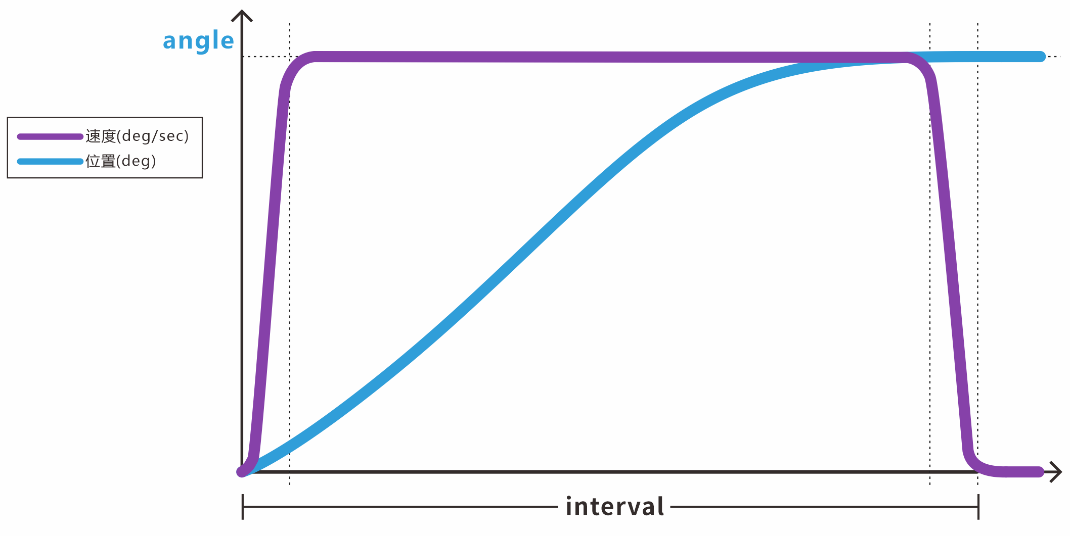
[-180°, +180°], making it especially suitable for continuous cable winding, slide rail drive, continuous turntables, and similar applications. - The control parameter logic and constraints are basically the same as single-turn mode, but the valid range of the target angle
angleis greatly expanded.
Simple Multi-Turn Angle Control
Function Prototype
FSUS_STATUS FSUS_SetServoAngleMTurn(
    Usart_DataTypeDef *usart,
    uint8_t servo_id,
    float angle,
    uint32_t interval,
    uint16_t power,
    uint8_t wait
);
Parameter Description
usart: Serial Port data objectUsart_DataTypeDefcorresponding to Servo control.servo_id: target Servo ID.angle: multi-turn target absolute angle. The minimum unit is 0.1°, and the value range expands to[-368640.0°, 368640.0°](about ±1024 turns).interval: expected motion run time (ms).power: maximum power limit (mV) for this motion. The default is0.wait: API blocking mode.0means non-blocking, where the API returns after the command is sent.1means blocking wait, where the API blocks until the Servo rotates into position.
Function Call Example
//// 舵机控制相关的参数
// 舵机的ID号
uint8_t servo_id = 0;
// 舵机的目标角度
float angle= 720.0f;
uint32_t interval = 2000;   // 运行时间ms
// 舵机执行功率,单位mV,默认为0
uint16_t power = 0;
 //  API是否为阻塞式,0:不等待 1:等待舵机旋转到特定的位置;
uint8_t wait = 0;

FSUS_SetServoAngleMTurn(servo_usart, servo_id, angle, interval, power, wait);
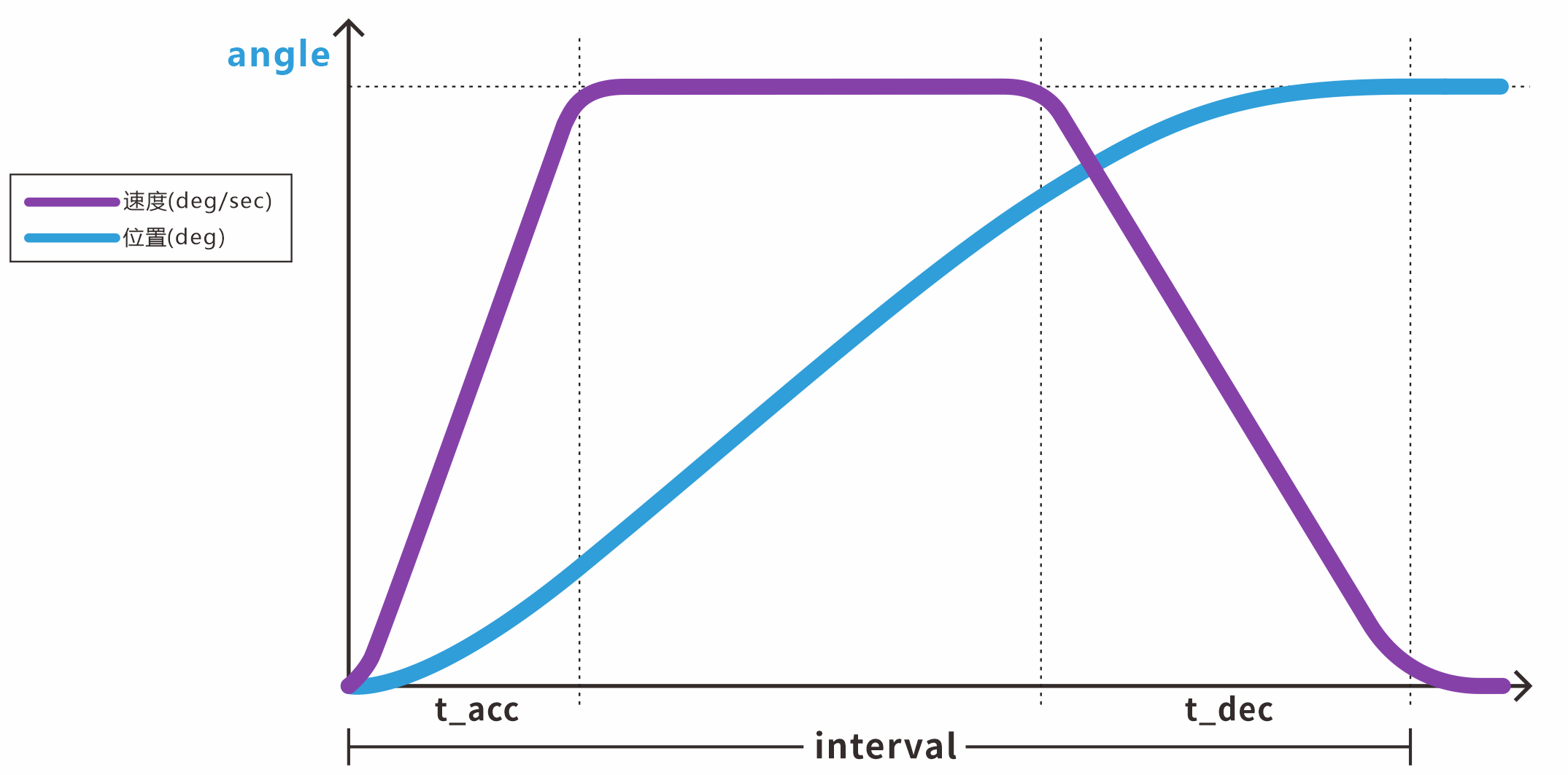
Advanced Multi-Turn Angle Control (Time-Based)
Function Prototype
FSUS_STATUS FSUS_SetServoAngleMTurnByInterval(
    Usart_DataTypeDef *usart,
    uint8_t servo_id,
    float angle,
    uint32_t interval,
    uint16_t t_acc,
    uint16_t t_dec,
    uint16_t power,
    uint8_t wait
);
Parameter Description
interval: total run time (ms), which must satisfyinterval > t_acc + t_dec.t_acc: time required to accelerate from rest to the constant-speed stage (ms), with a minimum value of> 20.t_dec: time required to decelerate from constant speed to stop (ms), with a minimum value of> 20. (Other parameters are the same as above.)
Function Call Example
//// 舵机控制相关的参数
// 舵机的ID号
uint8_t servo_id = 0;
// 舵机的目标角度
float angle= 720.0f;
uint32_t interval = 2000;   // 运行时间ms
// 舵机执行功率,单位mV,默认为0
uint16_t power = 0;
 //  API是否为阻塞式,0:不等待 1:等待舵机旋转到特定的位置;
uint8_t wait = 1;
// 加速时间(单位ms)
uint16_t t_acc = 100;
// 减速时间
uint16_t t_dec = 200;

FSUS_SetServoAngleMTurnByInterval(servo_usart, servo_id, angle, interval, t_acc, t_dec, power, wait);
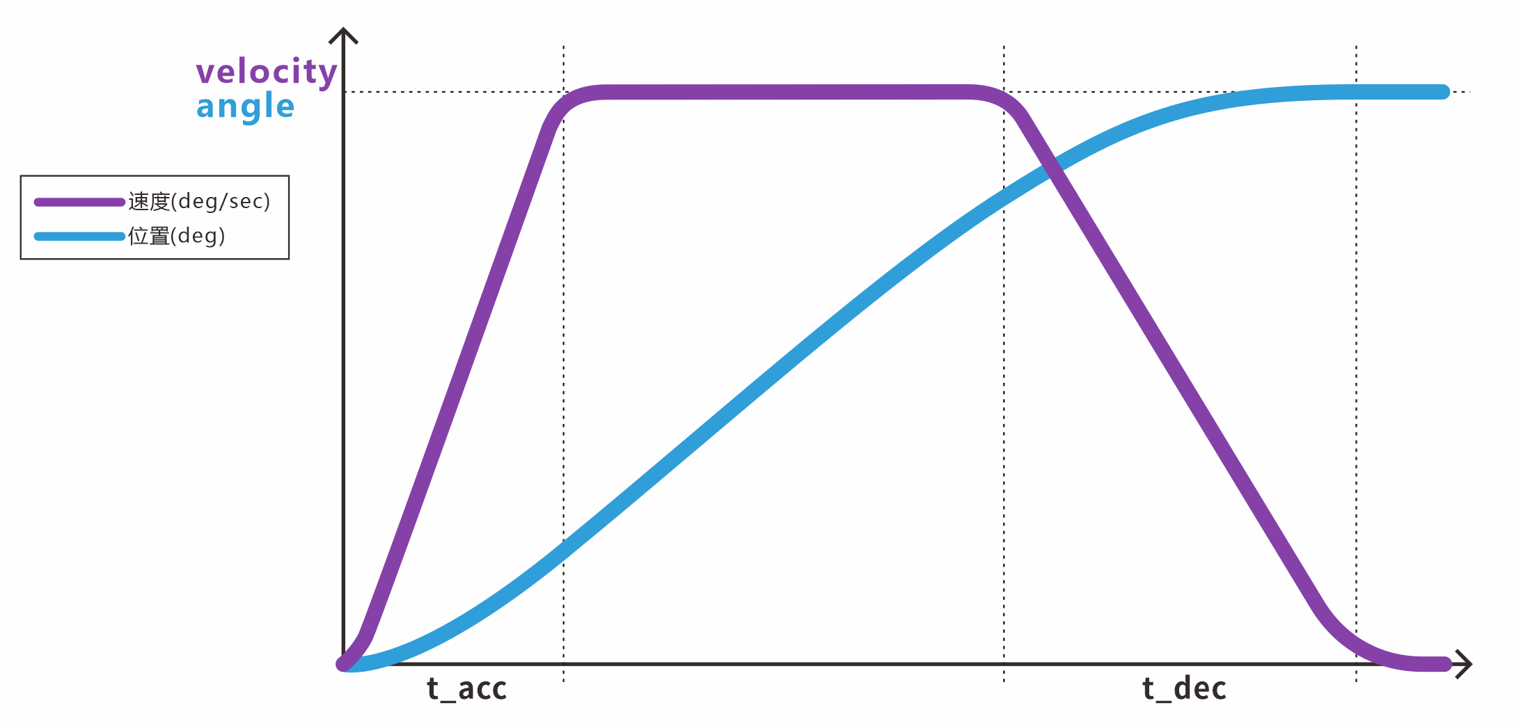
Advanced Multi-Turn Angle Control (Speed-Based)
Function Prototype
FSUS_STATUS FSUS_SetServoAngleMTurnByVelocity(
    Usart_DataTypeDef *usart,
    uint8_t servo_id,
    float angle,
    float velocity,
    uint16_t t_acc,
    uint16_t t_dec,
    uint16_t power,
    uint8_t wait
);
Parameter Description
velocity: target cruising speed in °/s. The valid range is[1, 750]. (Other parameters are the same as above.)
Function Call Example
//// 舵机控制相关的参数
// 舵机的ID号
uint8_t servo_id = 0;
// 舵机的目标角度
float angle= 720.0f;
float velocity = 100.0f;    // 电机转速, 单位dps,°/s
// 舵机执行功率,单位mV,默认为0
uint16_t power = 0;
 //  API是否为阻塞式,0:不等待 1:等待舵机旋转到特定的位置;
uint8_t wait = 1;
// 加速时间(单位ms)
uint16_t t_acc = 100;
// 减速时间
uint16_t t_dec = 200;

FSUS_SetServoAngleMTurnByVelocity(servo_usart, servo_id, angle, velocity, t_acc, t_dec, power, wait);
Read Current Multi-Turn Angle
Function Prototype
FSUS_STATUS FSUS_QueryServoAngleMTurn(
    Usart_DataTypeDef *usart,
    uint8_t servo_id,
    float *angle
);
Function Call Example
uint8_t servoId = 0;    // 舵机的ID号
float curAngle = 0;     // 舵机当前所在的角度
FSUS_QueryServoAngleMTurn(servoUsart, servoId, &curAngle); // 读取一下舵机的角度
//curAngle = 当前单圈角度
Reset Turn Count
Before resetting the turn count, send the stop command - release torque and unlock command first to make sure the servo is in a free state.
This command resets the turn count information of the servo and records the current absolute position angle as the current angle. The angle range is [-180.0, 180.0].
Function Prototype
FSUS_STATUS FSUS_ServoAngleReset(
    Usart_DataTypeDef *usart,
    uint8_t servo_id
);
Function Call Example
uint8_t servoId = 0;    // 舵机的ID号
FSUS_ServoAngleReset(servoUsart, servoId); // 清除多圈圈数
▶️ Multi-Turn Large-Angle Motion Control
Logic Description:
- Demonstrates rotating the servo by 720 degrees (two turns), then reversing it back to 0 degrees while printing the multi-turn angle in real time during control.
- This example demonstrates the three multi-turn angle control methods above and the API usage for querying the real-time multi-turn angle.
Complete Example Code:
/********************************************************
 * 舵机多圈控制模式演示
 ********************************************************/
#include "stm32f10x.h"
#include "usart.h"
#include "sys_tick.h"
#include "fashion_star_uart_servo.h"

// 使用串口1作为舵机控制的端口
// <接线说明>
// STM32F103 PA9(Tx)    <----> 总线伺服舵机转接板 Rx
// STM32F103 PA10(Rx)   <----> 总线伺服舵机转接板 Tx
// STM32F103 GND        <----> 总线伺服舵机转接板 GND
// STM32F103 V5         <----> 总线伺服舵机转接板 5V
// <注意事项>
// 使用前确保已设置usart.h里面的USART1_ENABLE为1
// 设置完成之后, 将下行取消注释
Usart_DataTypeDef* servo_usart = &usart1;

// 使用串口2作为日志输出的端口
// <接线说明>
// STM32F103 PA2(Tx) <----> USB转TTL Rx
// STM32F103 PA3(Rx) <----> USB转TTL Tx
// STM32F103 GND     <----> USB转TTL GND
// STM32F103 V5      <----> USB转TTL 5V (可选)
// <注意事项>
// 使用前确保已设置usart.h里面的USART2_ENABLE为1
// 设置完成之后, 将下行取消注释
Usart_DataTypeDef* loggingUsart = &usart2;

// 重定向c库函数printf到串口,重定向后可使用printf函数
int fputc(int ch, FILE *f)
{
    while((loggingUsart->pUSARTx->SR&0X40)==0){}
    /* 发送一个字节数据到串口 */
    USART_SendData(loggingUsart->pUSARTx, (uint8_t) ch);
    /* 等待发送完毕 */
    // while (USART_GetFlagStatus(USART1, USART_FLAG_TC) != SET);
    return (ch);
}


// 使用串口3作为舵机控制的端口
// <接线说明>
// STM32F103 PB10(Tx)   <----> 总线伺服舵机转接板 Rx
// STM32F103 PB11(Rx)   <----> 总线伺服舵机转接板 Tx
// STM32F103 GND        <----> 总线伺服舵机转接板 GND
// STM32F103 V5         <----> 总线伺服舵机转接板 5V
// <注意事项>
// 使用前确保已设置usart.h里面的USART1_ENABLE为1
// 设置完成之后, 将下行取消注释
// Usart_DataTypeDef* servo_usart = &usart3;

//// 舵机控制相关的参数
// 舵机的ID号
uint8_t servo_id = 0;
// 舵机的目标角度
// 舵机角度在-135度到135度之间, 精确到小数点后一位
float angle;
uint32_t interval;  // 运行时间ms
float velocity;         // 电机转速, 单位dps,°/s
// 舵机执行功率 单位mV,默认为0
uint16_t power = 0;
// 设置舵机角度的时候, 是否为阻塞式
// 0:不等待 1:等待舵机旋转到特定的位置;
uint8_t wait = 1;
// 加速时间(单位ms)
uint16_t t_acc;
// 减速时间
uint16_t t_dec;

// 读取的角度
float angle_read;
int main (void)
{
    // 嘀嗒定时器初始化
    SysTick_Init();
    // 串口初始化
    Usart_Init();

    while (1){
        printf("MTurn GOTO: 720.0f\r\n");
        //简易多圈角度控制 + 当前多圈角度查询
        angle = 720.0f;
        interval = 2000;
        FSUS_SetServoAngleMTurn(servo_usart, servo_id, angle, interval, power, wait);
        FSUS_QueryServoAngleMTurn(servo_usart, servo_id, &angle_read);
        printf("Cur Angle: %.1f\r\n", angle_read);

        // 等待2s
        SysTick_DelayMs(2000);


        printf("MTurn GOTO: 0.0f\r\n");
        angle = 0.0;
        FSUS_SetServoAngleMTurn(servo_usart, servo_id, angle, interval, power, wait);
        FSUS_QueryServoAngleMTurn(servo_usart, servo_id, &angle_read);
        printf("Cur Angle: %.1f\r\n", angle_read);

        // 等待2s
        SysTick_DelayMs(2000);


        //带加减速的多圈角度控制(指定周期) + 当前多圈角度查询
        printf("MTurn+Interval GOTO: -180.0f\r\n");
        angle = 180.0f;
        interval = 1000;
        t_acc = 100;
        t_dec = 200;
        FSUS_SetServoAngleMTurnByInterval(servo_usart, servo_id, angle, interval, t_acc, t_dec, power, wait);
        FSUS_QueryServoAngleMTurn(servo_usart, servo_id, &angle_read);
        printf("Cur Angle: %.1f\r\n", angle_read);

        // 等待2s
        SysTick_DelayMs(2000);

        //带加减速的多圈角度控制(指定转速) + 当前多圈角度查询
        printf("MTurn+Velocity GOTO: -180.0f\r\n");
        angle = -180.0f;
        velocity = 100.0f;
        t_acc = 100;
        t_dec = 200;
        FSUS_SetServoAngleMTurnByVelocity(servo_usart, servo_id, angle, velocity, t_acc, t_dec, power, wait);
        FSUS_QueryServoAngleMTurn(servo_usart, servo_id, &angle_read);
        printf("Cur Angle: %.1f\r\n", angle_read);

        // 等待2s
        SysTick_DelayMs(2000);

  }
}
Reference Terminal Output Log
MTurn GOTO: 720.0f
Cur Angle: 719.7
MTurn GOTO: 0.0f
Cur Angle: 0.4
MTurn+Interval GOTO: -180.0f
Cur Angle: 179.7
MTurn+Velocity GOTO: -180.0f
Cur Angle: -179.5
MTurn GOTO: 720.0f
Cur Angle: 719.5
MTurn GOTO: 0.0f
Cur Angle: 0.4
MTurn+Interval GOTO: -180.0f
Cur Angle: 179.7
MTurn+Velocity GOTO: -180.0f
Cur Angle: -179.5
▶️ Continuous Rotation of the Servo
Complete Example Code:
#include "stm32f10x.h"
#include "usart.h"
#include "sys_tick.h"
#include "fashion_star_uart_servo.h"

// 使用串口1作为舵机控制的端口
// <接线说明>
// STM32F103 PA9(Tx)  <----> 总线伺服舵机转接板 Rx
// STM32F103 PA10(Rx) <----> 总线伺服舵机转接板 Tx
// STM32F103 GND      <----> 总线伺服舵机转接板 GND
// STM32F103 V5       <----> 总线伺服舵机转接板 5V
// <注意事项>
// 使用前确保已设置usart.h里面的USART1_ENABLE为1
// 设置完成之后, 将下行取消注释
Usart_DataTypeDef* servoUsart = &usart1;

FSUS_STATUS statusCode; // 请求包的状态码
uint8_t servoId = 0;    // 连接在转接板上的总线伺服舵机ID号
uint16_t speed = 20;    // 舵机的旋转速度 20°/s
uint8_t is_cw = 0;      // 舵机的旋转方向
int main (void)
{
    // 嘀嗒定时器初始化
    SysTick_Init();
    // 串口初始化
    Usart_Init();

    while (1){
        // 舵机轮式模式定速控制 顺时针旋转3s
        is_cw = 1;
        FSUS_WheelKeepMove(servoUsart, servoId, is_cw, speed);
        SysTick_DelayMs(3000);

        // 舵机刹车 停顿2s
        FSUS_WheelStop(servoUsart, servoId);
        SysTick_DelayMs(1000);

        // 舵机轮式模式定速控制 逆时针旋转3s
        is_cw = 0;
        FSUS_WheelKeepMove(servoUsart, servoId, is_cw, speed);
        SysTick_DelayMs(3000);

        // 舵机刹车 停顿2s
        FSUS_WheelStop(servoUsart, servoId);
        SysTick_DelayMs(1000);
    }
}
▶️ Timed Rotation of the Servo
Complete Example Code:
/***************************************************
 * 轮式控制模式 定时旋转
 * <注意事项>
 * 在测试本例程时, 请确保舵机没有机械结构/接线的约束,
 * 舵机可以360度旋转
 ***************************************************/
#include "stm32f10x.h"
#include "usart.h"
#include "sys_tick.h"
#include "fashion_star_uart_servo.h"

// 使用串口1作为舵机控制的端口
// <接线说明>
// STM32F103 PA9(Tx)  <----> 总线伺服舵机转接板 Rx
// STM32F103 PA10(Rx) <----> 总线伺服舵机转接板 Tx
// STM32F103 GND      <----> 总线伺服舵机转接板 GND
// STM32F103 V5       <----> 总线伺服舵机转接板 5V
// <注意事项>
// 使用前确保已设置usart.h里面的USART1_ENABLE为1
// 设置完成之后, 将下行取消注释
Usart_DataTypeDef* servoUsart = &usart1;

FSUS_STATUS statusCode; // 请求包的状态码
uint8_t servoId = 0;    // 连接在转接板上的总线伺服舵机ID号
uint16_t speed = 20;    // 舵机的旋转速度 20°/s
uint8_t is_cw = 0;      // 舵机的旋转方向
uint16_t nTime = 3000;  // 延时时间
int main (void)
{
    // 嘀嗒定时器初始化
    SysTick_Init();
    // 串口初始化
    Usart_Init();

    while (1){
        // 舵机轮式模式定速控制 顺时针旋转3s
        is_cw = 1;
        FSUS_WheelMoveTime(servoUsart, servoId, is_cw, speed, nTime);
        // FSUS_WheelMoveTime是非阻塞的,因为有时候需要控制多个舵机同时旋转
        // 所以在后面要手动加延迟
        SysTick_DelayMs(nTime);

        // 停顿1s
        SysTick_DelayMs(1000);

        // 舵机轮式模式定速控制 逆时针旋转3s
        is_cw = 0;
        FSUS_WheelMoveTime(servoUsart, servoId, is_cw, speed, nTime);
        SysTick_DelayMs(nTime);

        // 停顿1s
        SysTick_DelayMs(1000);
    }
}
▶️ Fixed-Turn Rotation of the Servo
Complete Example Code:
/***************************************************
 * 轮式模式 定圈旋转
 * <注意事项>
 * 在测试本例程时, 请确保舵机没有机械结构/接线的约束,
 * 舵机可以360度旋转
 ***************************************************/
#include "stm32f10x.h"
#include "usart.h"
#include "sys_tick.h"
#include "fashion_star_uart_servo.h"

// 使用串口1作为舵机控制的端口
// <接线说明>
// STM32F103 PA9(Tx)  <----> 总线伺服舵机转接板 Rx
// STM32F103 PA10(Rx) <----> 总线伺服舵机转接板 Tx
// STM32F103 GND      <----> 总线伺服舵机转接板 GND
// STM32F103 V5       <----> 总线伺服舵机转接板 5V
// <注意事项>
// 使用前确保已设置usart.h里面的USART1_ENABLE为1
// 设置完成之后, 将下行取消注释
Usart_DataTypeDef* servoUsart = &usart1;

FSUS_STATUS statusCode; // 请求包的状态码
uint8_t servoId = 0;    // 连接在转接板上的总线伺服舵机ID号
uint16_t speed = 200;   // 舵机的旋转速度 单位°/s
uint8_t is_cw = 0;      // 舵机的旋转方向
uint16_t nCircle = 1;   // 舵机旋转的圈数

// 估计旋转圈数所需要花费的时间
uint16_t estimateTimeMs(uint16_t nCircle, uint16_t speed){
    return (uint16_t)((float)nCircle * 360.0 / (float)speed * 1000);
}

int main (void)
{
    // 嘀嗒定时器初始化
    SysTick_Init();
    // 串口初始化
    Usart_Init();

    while (1){
        // 舵机轮转模式定速控制 顺时针旋转1圈
        is_cw = 1;
        FSUS_WheelMoveNCircle(servoUsart, servoId, is_cw, speed, nCircle);
        // FSUS_WheelMoveNCircle是非阻塞的,因为有时候需要控制多个舵机同时旋转
        // 延时估算所需时间
        SysTick_DelayMs(estimateTimeMs(nCircle, speed));

        // 停顿1s
        SysTick_DelayMs(1000);

        // 舵机轮转模式定速控制 逆时针旋转1圈
        is_cw = 0;
        FSUS_WheelMoveNCircle(servoUsart, servoId, is_cw, speed, nCircle);
        // 注意: FSUS_WheelMoveNCircle是非阻塞的,因为有时候需要控制多个舵机同时旋转
        // 延时估算所需时间
        SysTick_DelayMs(estimateTimeMs(nCircle, speed));

        // 停顿1s
        SysTick_DelayMs(1000);
    }
}
7. Damping Mode
By adjusting the electromagnetic damping coefficient of the motor, the servo can provide a smooth resistance to external force, similar to being immersed in a viscous fluid, when it is no longer absolutely rigidly locked. This is well suited for passive teaching of robotic arms, gravity-drop buffering, and similar applications.
Function Prototype
// 舵机阻尼模式
FSUS_STATUS FSUS_DampingMode(
    Usart_DataTypeDef *usart,
    uint8_t servoId,
    uint16_t power
);
Parameter Description
usart: Serial Port data objectUsart_DataTypeDefcorresponding to Servo control.servoId: target Servo ID.power: response power for this damping mode, in mW. The higher the configured power, the stronger the hysteresis resistance felt when external force tries to rotate the Servo.
Function Call Example
// 连接在转接板上的总线伺服舵机ID号
uint8_t servoId = 0;
// 阻尼模式下的功率,功率越大阻力越大
uint16_t power = 500;
// 设置舵机为阻尼模式
FSUS_DampingMode(servoUsart, servoId, power);
▶️ Experience Damping Feel
Logic Description:
- After damping mode is enabled, the system idles and waits.
- You can directly rotate the output shaft of the servo by hand to feel the specific flexible resistance produced by
power = 500.
Complete Example Code:
/***************************************************
 * 总线伺服舵机阻尼模式
 ***************************************************/
#include "stm32f10x.h"
#include "usart.h"
#include "sys_tick.h"
#include "fashion_star_uart_servo.h"

// 使用串口1作为舵机控制的端口
// <接线说明>
// STM32F103 PA9(Tx)  <----> 总线伺服舵机转接板 Rx
// STM32F103 PA10(Rx) <----> 总线伺服舵机转接板 Tx
// STM32F103 GND      <----> 总线伺服舵机转接板 GND
// STM32F103 V5       <----> 总线伺服舵机转接板 5V
// <注意事项>
// 使用前确保已设置usart.h里面的USART1_ENABLE为1
// 设置完成之后, 将下行取消注释
Usart_DataTypeDef* servoUsart = &usart1;

// 连接在转接板上的总线伺服舵机ID号
uint8_t servoId = 0;
// 阻尼模式下的功率,功率越大阻力越大
uint16_t power = 500;
int main (void)
{
    // 嘀嗒定时器初始化
    SysTick_Init();
    // 串口初始化
    Usart_Init();
    // 设置舵机为阻尼模式
    FSUS_DampingMode(servoUsart, servoId, power);
    while (1)
    {
        //主循环什么也不做
        // 等待1000ms
        SysTick_DelayMs(1000);
    }
}
▶️ Damping Mode and Motion Trajectory Capture
Logic Description:
- Combines damping mode with position query to create an effect similar to robotic-arm motion teaching. The MCU captures and prints the drag trajectory created when you manually rotate the servo in real time.
Complete Example Code:
#include "stm32f10x.h"
#include "usart.h"
#include "sys_tick.h"
#include "fashion_star_uart_servo.h"

// 使用串口1作为舵机控制的端口
// <接线说明>
// STM32F103 PA9(Tx)  <----> 总线伺服舵机转接板 Rx
// STM32F103 PA10(Rx) <----> 总线伺服舵机转接板 Tx
// STM32F103 GND      <----> 总线伺服舵机转接板 GND
// STM32F103 V5       <----> 总线伺服舵机转接板 5V
// <注意事项>
// 使用前确保已设置usart.h里面的USART1_ENABLE为1
// 设置完成之后, 将下行取消注释
Usart_DataTypeDef* servoUsart = &usart1;
// 使用串口2作为日志输出的端口
// <接线说明>
// STM32F103 PA2(Tx) <----> USB转TTL Rx
// STM32F103 PA3(Rx) <----> USB转TTL Tx
// STM32F103 GND     <----> USB转TTL GND
// STM32F103 V5      <----> USB转TTL 5V (可选)
// <注意事项>
// 使用前确保已设置usart.h里面的USART2_ENABLE为1
Usart_DataTypeDef* loggingUsart = &usart2;

// 重定向c库函数printf到串口,重定向后可使用printf函数
int fputc(int ch, FILE *f)
{
    while((loggingUsart->pUSARTx->SR&0X40)==0){}
    /* 发送一个字节数据到串口 */
    USART_SendData(loggingUsart->pUSARTx, (uint8_t) ch);
    /* 等待发送完毕 */
    // while (USART_GetFlagStatus(USART1, USART_FLAG_TC) != SET);
    return (ch);
}

FSUS_STATUS statusCode; // 请求包的状态码
uint8_t servoId = 0;    // 连接在转接板上的总线伺服舵机ID号
uint16_t power = 500;   // 阻尼模式下的功率,功率越大阻力越大
float angle = 0;        // 舵机的角度

int main (void)
{
    // 嘀嗒定时器初始化
    SysTick_Init();
    // 串口初始化
    Usart_Init();
    // 设置舵机为阻尼模式
    FSUS_DampingMode(servoUsart, servoId, power);
    while (1)
    {
        // 读取一下舵机的角度
        statusCode = FSUS_QueryServoAngle(servoUsart, servoId, &angle);

        if (statusCode ==FSUS_STATUS_SUCCESS){
            // 成功的读取到了舵机的角度
            printf("[INFO] servo id= %d ; angle = %f\r\n", servoId, angle);
        }else{
            // 没有正确的读取到舵机的角度
            printf("\r\n[INFO] read servo %d angle, status code: %d \r\n", servoId, statusCode);
            printf("[ERROR]failed to read servo angle\r\n");
        }
        // 等待1000ms
        SysTick_DelayMs(500);
    }
}
8. Stop Command
Three stop modes are provided: stop and release torque, hold the current position with torque, and enter damping mode.
This command can also be used to enable servo torque. When the servo servo is unlocked, sending the hold torque command makes it rebuild holding torque from its current position.
Function Prototype
FSUS_STATUS FSUS_StopOnControlMode(
    Usart_DataTypeDef *usart,
    uint8_t servo_id,
    uint8_t mode,
    uint16_t power
);
Parameter Description
usart: Serial Port data objectUsart_DataTypeDefcorresponding to Servo control.servo_id: target Servo ID.mode: stop mode number.0- fully release torque and unlock, so the shaft can be moved freely.1- hold absolute position with torque, locking the current position.2- enter electromagnetic damping mode with flexible hysteresis.power: if2(damping) is selected, this parameter sets the effective power limit after entering damping mode (mW).
Function Call Example
/* 舵机控制模式停止指令*/
//mode 指令停止形式
//0-停止后卸力(失锁)
//1-停止后保持锁力
//2-停止后进入阻尼状态
uint8_t stopcolmode=0;
uint8_t servo_id = 0;   // 连接在转接板上的总线伺服舵机ID号
uint16_t power = 500;  //功率
FSUS_StopOnControlMode(servoUsart, servo_id, stopcolmode, power);
▶️ Automatically Switch to Damping After Motion Completes
Logic Description:
- Demonstrates a typical workflow: command the servo motion -> wait until its motion cycle completes -> immediately switch the internal electric control mode to
stopcolmode=2to enter damping mode.
Complete Example Code:
/********************************************************
* 控制舵机执行完指令进入阻尼状态
 ********************************************************/
#include "stm32f10x.h"
#include "usart.h"
#include "sys_tick.h"
#include "fashion_star_uart_servo.h"

// 使用串口1作为舵机控制的端口
// <接线说明>
// STM32F103 PA9(Tx)    <----> 总线伺服舵机转接板 Rx
// STM32F103 PA10(Rx)   <----> 总线伺服舵机转接板 Tx
// STM32F103 GND        <----> 总线伺服舵机转接板 GND
// STM32F103 V5         <----> 总线伺服舵机转接板 5V
// <注意事项>
// 使用前确保已设置usart.h里面的USART1_ENABLE为1
Usart_DataTypeDef* servo_usart = &usart1;

// 使用串口2作为日志输出的端口
// <接线说明>
// STM32F103 PA2(Tx) <----> USB转TTL Rx
// STM32F103 PA3(Rx) <----> USB转TTL Tx
// STM32F103 GND     <----> USB转TTL GND
// STM32F103 V5      <----> USB转TTL 5V (可选)
Usart_DataTypeDef* logging_usart = &usart2;

// 重定向c库函数printf到串口,重定向后可使用printf函数
int fputc(int ch, FILE *f)
{
    while((logging_usart->pUSARTx->SR&0X40)==0){}
    /* 发送一个字节数据到串口 */
    USART_SendData(logging_usart->pUSARTx, (uint8_t) ch);
    /* 等待发送完毕 */
    // while (USART_GetFlagStatus(USART1, USART_FLAG_TC) != SET);
    return (ch);
}


//0-停止后卸力(失锁)
//1-停止后保持锁力
//2-停止后进入阻尼状态
uint8_t stopcolmode=2;

float   angle = 135.0;// 舵机的目标角度
uint16_t interval = 1000;// 时间间隔ms
uint16_t    power = 500;// 舵机执行功率
uint8_t servo_id=0;// 舵机的ID号

int main (void)
{
    // 嘀嗒定时器初始化
    SysTick_Init();
    // 串口初始化
    Usart_Init();

    FSUS_SetServoAngle(servo_usart, servo_id, angle, interval, power);
    SysTick_DelayMs(2000);

    //停止后进入对应状态
    FSUS_StopOnControlMode(servo_usart, servo_id, stopcolmode, power);
    SysTick_DelayMs(1000);
    while (1){

  }
}
9. Synchronous Commands
When developing multi-axis linkage equipment such as robotic arms and humanoid robots, ordinary polling-style serial communication can introduce small timing differences as each joint receives commands, causing the motion posture to deform.
FSUS_SyncCommand allows the host to package the target parameters of all joints into one long command and send it to the bus at once. All online servo are triggered almost simultaneously at the hardware level, helping reproduce the kinematic algorithm accurately.
Function Prototype
FSUS_STATUS FSUS_SyncCommand(
    Usart_DataTypeDef *usart,
    uint8_t servo_count,
    uint8_t ServoMode,
    FSUS_sync_servo servoSync[]
);
Parameter Description
usart: Serial Port data objectUsart_DataTypeDefcorresponding to Servo control.servo_count: number of Servo participating in this synchronous control operation.ServoMode: declares the specific purpose of this group-control command batch.1: simple angle control2: angle control with acceleration and deceleration (specified cycle)3: angle control with acceleration and deceleration (specified speed)4: simple multi-turn angle control5: multi-turn angle control with acceleration and deceleration (specified cycle)6: multi-turn angle control with acceleration and deceleration (specified speed)7: data monitoringservoSync[]: core structure array used to store the control parameters to be sent to each node.
Function Call Example
/*同步指令模式选择
* 1:设置舵机的角度
* 2:设置舵机的角度(指定周期)
* 3:设置舵机的角度(指定转速)
* 4:设置舵机的角度(多圈模式)
* 5:设置舵机的角度(多圈模式, 指定周期)
* 6:设置舵机的角度(多圈模式, 指定转速)
* 7:读取舵机的数据*/
uint8_t sync_mode=1;//同步指令模式

uint8_t sync_count=5;//舵机数量

//数组定义在#include "fashion_star_uart_servo.c"
FSUS_sync_servo SyncArray[20]; // 假设您要控制20个伺服同步
ServoData servodata[20];//假设您要读取20个伺服舵机的数据

//如需更改舵机数量在#include "fashion_star_uart_servo.h"对应修改extern
extern FSUS_sync_servo SyncArray[20]; // 假设您要控制20个伺服同步
extern ServoData servodata[20];//假设您要读取20个伺服舵机的数据

servoSyncArray[0].angle=90;/*角度*/
servoSyncArray[0].id=0;/*舵机ID号*/
servoSyncArray[0].velocity=100;/*速度*/                servoSyncArray[0].interval_single=1000;/*单圈时间*/    servoSyncArray[0].interval_multi=1000; /*多圈时间*/     servoSyncArray[0].t_acc=100;/*加速时间*/
servoSyncArray[0].t_dec=100;/*减速时间*/                servoSyncArray[0].power=100;/*功率*/
/*********************************以此类推赋值剩下舵机参数 灵活性高**************************************/

FSUS_SyncCommand(servo_usart, servo_count, servomode, servoSyncArray);
▶️ System-Level Millisecond Synchronous Coordination
Logic Description:
- Demonstrates how to fill the
SyncArraystructure, package the control parameters of five servo (ID: 0-4), and broadcast them to the bus so that all axes can start synchronously with high real-time performance and reach the target pose. - Immediately broadcasts mode 7 afterward to read the latest system status.
Complete Example Code:
#include "stm32f10x.h"
#include "usart.h"
#include "sys_tick.h"
#include "fashion_star_uart_servo.h"

// 使用串口1作为舵机控制的端口
// <接线说明>
// STM32F103 PA9(Tx)  <----> 总线伺服舵机转接板 Rx
// STM32F103 PA10(Rx) <----> 总线伺服舵机转接板 Tx
// STM32F103 GND      <----> 总线伺服舵机转接板 GND
// STM32F103 V5       <----> 总线伺服舵机转接板 5V
// <注意事项>
// 使用前确保已设置usart.h里面的USART1_ENABLE为1
// 设置完成之后, 将下行取消注释
Usart_DataTypeDef* servoUsart = &usart1;

// 使用串口2作为日志输出的端口
// <接线说明>
// STM32F103 PA2(Tx) <----> USB转TTL Rx
// STM32F103 PA3(Rx) <----> USB转TTL Tx
// STM32F103 GND     <----> USB转TTL GND
// STM32F103 V5      <----> USB转TTL 5V (可选)
Usart_DataTypeDef* logging_usart = &usart2;


// 重定向c库函数printf到串口,重定向后可使用printf函数
int fputc(int ch, FILE *f)
{
    while((logging_usart->pUSARTx->SR&0X40)==0){}
    /* 发送一个字节数据到串口 */
    USART_SendData(logging_usart->pUSARTx, (uint8_t) ch);
    /* 等待发送完毕 */
    // while (USART_GetFlagStatus(USART1, USART_FLAG_TC) != SET);
    return (ch);
}

/*同步指令模式选择
* 1:设置舵机的角度
* 2:设置舵机的角度(指定周期)
* 3:设置舵机的角度(指定转速)
* 4:设置舵机的角度(多圈模式)
* 5:设置舵机的角度(多圈模式, 指定周期)
* 6:设置舵机的角度(多圈模式, 指定转速)
* 7:读取舵机的数据*/
uint8_t servomode=1;//自行更改数值设置模式

//舵机数量,如果id不是从0开始,请把参数设置为最大舵机id号
uint8_t servo_count=5;

int main (void)
{
    // 嘀嗒定时器初始化
    SysTick_Init();
    // 串口初始化
    Usart_Init();

    while (1){

    SyncArray[0].angle=90;
        SyncArray[0].id=0;SyncArray[0].interval_single=100;SyncArray[0].interval_multi=1000;SyncArray[0].velocity=100;SyncArray[0].t_acc=20;SyncArray[0].t_dec=20;
        SyncArray[1].angle=-90;
        SyncArray[1].id=1;SyncArray[1].interval_single=100;SyncArray[1].interval_multi=1000;SyncArray[1].velocity=100;SyncArray[1].t_acc=20;SyncArray[1].t_dec=20;
        SyncArray[2].angle=90;
        SyncArray[2].id=2;SyncArray[2].interval_single=100;SyncArray[2].interval_multi=1000;SyncArray[2].velocity=100;SyncArray[2].t_acc=20;SyncArray[2].t_dec=20;
        SyncArray[3].angle=-90;
        SyncArray[3].id=3;SyncArray[3].interval_single=100;SyncArray[3].interval_multi=1000;SyncArray[3].velocity=100;SyncArray[3].t_acc=20;SyncArray[3].t_dec=20;
        SyncArray[4].angle=-90;
        SyncArray[4].id=4;SyncArray[4].interval_single=100;SyncArray[4].interval_multi=1000;SyncArray[4].velocity=100;SyncArray[4].t_acc=20;SyncArray[4].t_dec=20;
        //发送同步指令控制
        FSUS_SyncCommand(servo_usart,sync_count,servomode,SyncArray);
        SysTick_DelayMs(1000);
        //发送同步指令读取
        FSUS_SyncCommand(servo_usart,sync_count,7,SyncArray);
        SysTick_DelayMs(200);

        SyncArray[0].angle=45;SyncArray[0].interval_single=0;SyncArray[0].velocity=20;
        SyncArray[1].angle=-45;SyncArray[1].interval_single=0;SyncArray[1].velocity=20;
        SyncArray[2].angle=45;SyncArray[2].interval_single=0;SyncArray[2].velocity=20;
        SyncArray[3].angle=-45;SyncArray[3].interval_single=0;SyncArray[3].velocity=20;
        SyncArray[4].angle=-45;SyncArray[4].interval_single=0;SyncArray[4].velocity=20;
        //发送同步指令控制
        FSUS_SyncCommand(servo_usart,sync_count,servomode,SyncArray);
        SysTick_DelayMs(1000);
        //发送同步指令读取
        FSUS_SyncCommand(servo_usart,sync_count,7,SyncArray);
        SysTick_DelayMs(200);
  }
}
10. Asynchronous Commands (Temporary Storage and Delayed Trigger)
Asynchronous commands allow the host to write motion commands into the internal register cache of the servo in advance, like a memo. At this stage, the servo does not execute them.
Only when the host determines that the time is right and sends an asynchronous execution enable command to the bus does the servo immediately start executing the stored motion. This is especially suitable for building complex distributed trigger networks.
Asynchronous Write (Enable Asynchronous Command Storage Mode)
Function Prototype
FSUS_STATUS FSUS_BeginAsync(
    Usart_DataTypeDef *usart
);
- Parameter Description
usart: Serial Port data objectUsart_DataTypeDefcorresponding to Servo control.
Function Call Example
FSUS_BeginAsync(servo_usart); // 通知底层:后续指令不要立刻跑,先缓存起来
Asynchronous Execution (End Asynchronous Mode and Execute/Discard)
Function Prototype
FSUS_STATUS FSUS_EndAsync(
    Usart_DataTypeDef *usart,
    uint8_t mode
);
Parameter Description
* mode: terminal logic trigger flag. 0 approves execution of the stored motion, while 1 discards and clears the stored motion.
Function Call Example
uint8_t async_mode=0; //0:执行存储的命令  1:取消存储的命令
FSUS_EndAsync(servo_usart,async_mode);
▶️ Delayed Trigger for Asynchronous Commands
Logic Description:
- Demonstrates sending an angle command after enabling the system asynchronous switch. At this moment, the device remains still.
- After the MCU actively sleeps and blocks for a 5-second delay, it sends the End command to confirm execution and wake the underlying hardware.
Complete Example Code:
/********************************************************
 * 存储一次命令,在下次发送命令的时候才执行
 ********************************************************/
#include "stm32f10x.h"
#include "usart.h"
#include "sys_tick.h"
#include "fashion_star_uart_servo.h"

// 使用串口1作为舵机控制的端口
// <接线说明>
// STM32F103 PA9(Tx)    <----> 总线伺服舵机转接板 Rx
// STM32F103 PA10(Rx)   <----> 总线伺服舵机转接板 Tx
// STM32F103 GND        <----> 总线伺服舵机转接板 GND
// STM32F103 V5         <----> 总线伺服舵机转接板 5V
// <注意事项>
// 使用前确保已设置usart.h里面的USART1_ENABLE为1
Usart_DataTypeDef* servo_usart = &usart1;

// 使用串口2作为日志输出的端口
// <接线说明>
// STM32F103 PA2(Tx) <----> USB转TTL Rx
// STM32F103 PA3(Rx) <----> USB转TTL Tx
// STM32F103 GND     <----> USB转TTL GND
// STM32F103 V5      <----> USB转TTL 5V (可选)
Usart_DataTypeDef* logging_usart = &usart2;


// 重定向c库函数printf到串口,重定向后可使用printf函数
int fputc(int ch, FILE *f)
{
    while((logging_usart->pUSARTx->SR&0X40)==0){}
    /* 发送一个字节数据到串口 */
    USART_SendData(logging_usart->pUSARTx, (uint8_t) ch);
    /* 等待发送完毕 */
    // while (USART_GetFlagStatus(USART1, USART_FLAG_TC) != SET);
    return (ch);
}


#define ID 0 // 舵机的ID号
float angle;           //舵机角度设置
float angle_read;            // 读取的角度
uint16_t power = 1000; // 舵机执行功率 单位mV 默认为0
uint16_t interval = 0; // 舵机旋转的周期

uint8_t async_mode=0; //0:执行存储的命令  1:取消存储的命令

int main (void)
{
    // 嘀嗒定时器初始化
    SysTick_Init();
    // 串口初始化
    Usart_Init();

    while (1){

    //异步写入
        FSUS_BeginAsync(servo_usart);

        printf("GOTO: 135.0f\r\n");
    // 简易角度控制 + 当前角度查询
    angle = 135.0;
    interval = 2000;
    FSUS_SetServoAngle(servo_usart, ID, angle, interval, power);
    FSUS_QueryServoAngle(servo_usart, ID, &angle_read);
    printf("Cur Angle: %.1f\r\n", angle_read);

        printf("*******************\n");

    //第一次发送上面的命令是不会动的,只是存储了命令
    //等待5秒
        SysTick_DelayMs(5000);

        //异步执行
        FSUS_EndAsync(servo_usart,async_mode);
  }
}
11. Data Monitoring (Batch Read)
Compared with reading each physical parameter one by one, the system provides the FSUS_ServoMonitor function, which loads the complete status data of the servo into one structure at once and greatly reduces bus communication occupancy time.
Function Prototype
FSUS_STATUS FSUS_ServoMonitor(
    Usart_DataTypeDef *usart,
    uint8_t servo_id,
    ServoData servodata[]
);
Parameter Description
usart: Serial Port data objectUsart_DataTypeDefcorresponding to Servo control.-
servoId: target Servo ID. -
servodata[]: pointer to the receive structure object used to store the complete status data of the Servo.
packet includes:
Function Call Example
//要读取的舵机id号
uint8_t servoId = 0;
//舵机的存储数据结构体
ServoData servodata_single[1];
// 读取舵机数据函数
FSUS_ServoMonitor(servo_usart,servo_id,servodata_single);
▶️ Full Monitoring of Servo Sensor Data
Logic Description:
- After initializing the servo, periodically sends Monitor requests to the lower layer. It then accesses member variables of
servodata_single, such asvoltage,current,power,temperature, andangle, to format and output real-time hardware status to the UART2 configuration port.
Complete Example Code:
/********************************************************
 * 测试舵机的数据回读,并通过串口打印全部数据
 ********************************************************/
#include "stm32f10x.h"
#include "usart.h"
#include "sys_tick.h"
#include "fashion_star_uart_servo.h"

// 使用串口1作为舵机控制的端口
// <接线说明>
// STM32F103 PA9(Tx)    <----> 总线伺服舵机转接板 Rx
// STM32F103 PA10(Rx)   <----> 总线伺服舵机转接板 Tx
// STM32F103 GND        <----> 总线伺服舵机转接板 GND
// STM32F103 V5         <----> 总线伺服舵机转接板 5V
// <注意事项>
// 使用前确保已设置usart.h里面的USART1_ENABLE为1
Usart_DataTypeDef* servo_usart = &usart1;

// 使用串口2作为日志输出的端口
// <接线说明>
// STM32F103 PA2(Tx) <----> USB转TTL Rx
// STM32F103 PA3(Rx) <----> USB转TTL Tx
// STM32F103 GND     <----> USB转TTL GND
// STM32F103 V5      <----> USB转TTL 5V (可选)
Usart_DataTypeDef* logging_usart = &usart2;


// 重定向c库函数printf到串口,重定向后可使用printf函数
int fputc(int ch, FILE *f)
{
    while((logging_usart->pUSARTx->SR&0X40)==0){}
    /* 发送一个字节数据到串口 */
    USART_SendData(logging_usart->pUSARTx, (uint8_t) ch);
    /* 等待发送完毕 */
    // while (USART_GetFlagStatus(USART1, USART_FLAG_TC) != SET);
    return (ch);
}

/*数据监控的数据
* id:舵机的id号
* voltage:舵机的电压
* current:舵机的电流
* power:舵机的执行功率
* temperature:舵机的温度
* status:舵机的状态
* angle:舵机的角度
* circle_count:舵机的转动圈数
*/
ServoData servodata_single[1];//读取一个舵机数据的结构体

//要读取的舵机id号
uint8_t servo_id=0;

int main (void)
{
    // 嘀嗒定时器初始化
    SysTick_Init();
    // 串口初始化
    Usart_Init();
    while (1){
            //每1秒读取一次
            FSUS_DampingMode(servo_usart,servo_id,500);
            FSUS_ServoMonitor(servo_usart,servo_id,servodata_single);
            printf("read ID: %d\r\n", servodata_single[0].id);
            printf("read sucess, voltage: %d mV\r\n", servodata_single[0].voltage);
            printf("read sucess, current: %d mA\r\n", servodata_single[0].current);
            printf("read sucess, power: %d mW\r\n", servodata_single[0].power);
            printf("read sucess, temperature: %d \r\n", servodata_single[0].temperature);
            if ((servodata_single[0].status >> 3) & 0x01)
            printf("read sucess, voltage too high\r\n");
            if ((servodata_single[0].status >> 4) & 0x01)
            printf("read sucess, voltage too low\r\n");
            printf("read sucess, angle: %f\r\n", servodata_single[0].angle);
            printf("read sucess, circle_count: %d\r\n",servodata_single[0].circle_count);
            SysTick_DelayMs(1000);

  }
}
12. Origin Setting
Before triggering origin reset, send the stop command - release torque and unlock command first to make sure the servo is in a free state.
Function Prototype
FSUS_STATUS FSUS_SetOriginPoint(
    Usart_DataTypeDef *usart,
    uint8_t servo_id
);
Parameter Description
usart: Serial Port data objectUsart_DataTypeDefcorresponding to Servo control.servo_id: target Servo ID.
Function Call Example
uint8_t servoId = 0;    // 舵机的ID号
FSUS_SetOriginPoint(servoUsart, servoId); // 将当前物理结构位置重新映射为固件级 0 度
13. Read and Write Servo Custom Configuration Parameters
In some cases, you may only need to read or modify one specific hardware register address in the servo memory table, such as voltage or protection values.
Function Prototype
// 读取数据
FSUS_STATUS FSUS_ReadData(
    Usart_DataTypeDef *usart,
    uint8_t servoId,
    uint8_t address,
    uint8_t *value,
    uint8_t *size
);
Parameter Description
usart: Serial Port data objectUsart_DataTypeDefcorresponding to Servo control.-
servo_id: target Servo ID. -
address: start address number of the queried parameter in the internal memory table of the Servo. See the appendix table for details. value: receive buffer pointer used to store the readback data.size: returns the actual byte length of valid data at this address (1, 2, or 4 bytes).
Function Call Example
uint8_t servoId = 0;        // 连接在转接板上的总线伺服舵机ID号
uint8_t value;
uint8_t dataSize;

statusCode = FSUS_ReadData(servoUsart, servoId, FSUS_PARAM_SERVO_STATUS, (uint8_t *)&value, &dataSize);

if (statusCode == FSUS_STATUS_SUCCESS)
{
    // 舵机工作状态标志位
    // BIT[0] - 执行指令置1,执行完成后清零。
    // BIT[1] - 执行指令错误置1,在下次正确执行后清零。
    // BIT[2] - 堵转错误置1,解除堵转后清零。
    // BIT[3] - 电压过高置1,电压恢复正常后清零。
    // BIT[4] - 电压过低置1,电压恢复正常后清零。
    // BIT[5] - 电流错误置1,电流恢复正常后清零。
    // BIT[6] - 功率错误置1,功率恢复正常后清零。
    // BIT[7] - 温度错误置1,温度恢复正常后清零。

    if ((value >> 3) & 0x01)
        printf("read sucess, voltage too high\r\n");
    if ((value >> 4) & 0x01)
        printf("read sucess, voltage too low\r\n");
}
Parameter Write
Warning
- For key non-volatile parameters such as ID and baud rate, we strongly recommend using the Windows PC configuration software visual software.
- Use this API for runtime code-level modification only when necessary. Incorrect modification may cause abnormal device behavior.
Function Prototype
// 写入数据
FSUS_STATUS FSUS_WriteData(
    Usart_DataTypeDef *usart,
    uint8_t servoId,
    uint8_t address,
    uint8_t *value,
    uint8_t size
);
Function Call Example
uint8_t servoId = 0;        // 连接在转接板上的总线伺服舵机ID号
float angleLimitLow = -90.0;    // 舵机角度下限设定值
value = (int16_t)(angleLimitLow*10); // 舵机角度下限 转换单位为0.1度
statusCode = FSUS_WriteData(servoUsart, servoId, FSUS_PARAM_ANGLE_LIMIT_LOW, (uint8_t *)&value, 2);
▶️ Read Servo Parameters
Logic Description:
- Shows how to use the low-level communication layer
FSUS_ReadDatafunction. -
The code demonstrates reading voltage, current, power, and temperature ADC values. It also shows the underlying mathematical formula for converting the temperature ADC value to Celsius, and uses bit operations to parse the 8-bit
statusstatus register flags.// servo operating status flag bits // BIT[0] - set to 1 while a command is executing, cleared after execution is complete. // BIT[1] - set to 1 when command execution fails, cleared after the next correct execution. // BIT[2] - set to 1 for stall protection, cleared after the stall is resolved. // BIT[3] - set to 1 for overvoltage, cleared after voltage returns to normal. // BIT[4] - set to 1 for undervoltage, cleared after voltage returns to normal. // BIT[5] - set to 1 for current protection, cleared after current returns to normal. // BIT[6] - set to 1 for power protection, cleared after power returns to normal. // BIT[7] - set to 1 for temperature protection, cleared after temperature returns to normal.
Complete Example Code:
/***************************************************
* 读取舵机参数
 ***************************************************/
#include "stm32f10x.h"
#include "usart.h"
#include "sys_tick.h"
#include "fashion_star_uart_servo.h"
#include "math.h"

// 使用串口1作为舵机控制的端口
// <接线说明>
// STM32F103 PA9(Tx)  <----> 总线伺服舵机转接板 Rx
// STM32F103 PA10(Rx) <----> 总线伺服舵机转接板 Tx
// STM32F103 GND      <----> 总线伺服舵机转接板 GND
// STM32F103 V5       <----> 总线伺服舵机转接板 5V
// <注意事项>
// 使用前确保已设置usart.h里面的USART1_ENABLE为1
// 设置完成之后, 将下行取消注释
Usart_DataTypeDef *servoUsart = &usart1;

// 使用串口2作为日志输出的端口
// <接线说明>
// STM32F103 PA2(Tx) <----> USB转TTL Rx
// STM32F103 PA3(Rx) <----> USB转TTL Tx
// STM32F103 GND     <----> USB转TTL GND
// STM32F103 V5      <----> USB转TTL 5V (可选)
// <注意事项>
// 使用前确保已设置usart.h里面的USART2_ENABLE为1
Usart_DataTypeDef *loggingUsart = &usart2;

// 重定向c库函数printf到串口,重定向后可使用printf函数
int fputc(int ch, FILE *f)
{
    while ((loggingUsart->pUSARTx->SR & 0X40) == 0)
    {
    }
    /* 发送一个字节数据到串口 */
    USART_SendData(loggingUsart->pUSARTx, (uint8_t)ch);
    /* 等待发送完毕 */
    // while (USART_GetFlagStatus(USART1, USART_FLAG_TC) != SET);
    return (ch);
}

uint8_t servoId = 0;    // 连接在转接板上的总线伺服舵机ID号
FSUS_STATUS statusCode; // 状态码

int main(void)
{
    // 嘀嗒定时器初始化
    SysTick_Init();
    // 串口初始化
    Usart_Init();

    // 读取用户自定义数据
    // 数据表里面的数据字节长度一般为1个字节/2个字节/4个字节
    // 查阅通信协议可知,舵机角度上限的数据类型是有符号短整型(UShort, 对应STM32里面的int16_t),长度为2个字节
    // 所以这里设置value的数据类型为int16_t
    int16_t value;
    uint8_t dataSize;
    // 传参数的时候, 要将value的指针强行转换为uint8_t

    // 读取电压
    statusCode = FSUS_ReadData(servoUsart, servoId, FSUS_PARAM_VOLTAGE, (uint8_t *)&value, &dataSize);

    printf("read ID: %d\r\n", servoId);

    if (statusCode == FSUS_STATUS_SUCCESS)
    {
        printf("read sucess, voltage: %d mV\r\n", value);
    }
    else
    {
        printf("fail\r\n");
    }

    // 读取电流
    statusCode = FSUS_ReadData(servoUsart, servoId, FSUS_PARAM_CURRENT, (uint8_t *)&value, &dataSize);
    if (statusCode == FSUS_STATUS_SUCCESS)
    {
        printf("read sucess, current: %d mA\r\n", value);
    }
    else
    {
        printf("fail\r\n");
    }

    // 读取功率
    statusCode = FSUS_ReadData(servoUsart, servoId, FSUS_PARAM_POWER, (uint8_t *)&value, &dataSize);
    if (statusCode == FSUS_STATUS_SUCCESS)
    {
        printf("read sucess, power: %d mW\r\n", value);
    }
    else
    {
        printf("fail\r\n");
    }
    // 读取温度
    statusCode = FSUS_ReadData(servoUsart, servoId, FSUS_PARAM_TEMPRATURE, (uint8_t *)&value, &dataSize);
    if (statusCode == FSUS_STATUS_SUCCESS)
    {
        double temperature, temp;
        temp = (double)value;
        temperature = 1 / (log(temp / (4096.0f - temp)) / 3435.0f + 1 / (273.15 + 25)) - 273.15;
        printf("read sucess, temperature: %f\r\n", temperature);
    }
    else
    {
        printf("fail\r\n");
    }
    // 读取工作状态
    statusCode = FSUS_ReadData(servoUsart, servoId, FSUS_PARAM_SERVO_STATUS, (uint8_t *)&value, &dataSize);
    if (statusCode == FSUS_STATUS_SUCCESS)
    {
        // 舵机工作状态标志位
        // BIT[0] - 执行指令置1,执行完成后清零。
        // BIT[1] - 执行指令错误置1,在下次正确执行后清零。
        // BIT[2] - 堵转保护置1,解除堵转后清零。
        // BIT[3] - 电压过高置1,电压恢复正常后清零。
        // BIT[4] - 电压过低置1,电压恢复正常后清零。
        // BIT[5] - 电流保护置1,电流恢复正常后清零。
        // BIT[6] - 功率保护置1,功率恢复正常后清零。
        // BIT[7] - 温度保护置1,温度恢复正常后清零。

        if ((value >> 3) & 0x01)
            printf("read sucess, voltage too high\r\n");
        if ((value >> 4) & 0x01)
            printf("read sucess, voltage too low\r\n");
    }
    else
    {
        printf("fail\r\n");
    }
    printf("================================= \r\n");
    // 死循环
    while (1)
        ;
}
Reference Terminal Output Log
read ID: 0                                      //舵机id
read success, voltage: 8905 mv                 //当前电压
read success, current: 0 ma                    //当前电流
read success, power: 0 mw                      //当前功率
read success, temperature: 32.240993           //当前温度
read success, voltage too high                 //如果当前电压超过舵机参数设置的舵机高压保护值,可以读到标志位
=================================
=== Part 3: Appendix Quick Reference Tables ===
Appendix Table 1: Read-Only Parameter Table
Use this table with the address parameter of the FSUS_ReadData function.
| Address | Parameter Name | Data Type | Unit | Remarks |
|---|---|---|---|---|
| 1 | Voltage | uint16_t | mV | |
| 2 | Current | uint16_t | mA | |
| 3 | Power | uint16_t | mW | |
| 4 | Temperature | uint16_t | ADC | Refer to the [ADC-Temperature Mapping Table] |
| 5 | Status Flags | uint8_t | BIT[0] - set to 1 while command execution is in progress, cleared after execution completes BIT[1] - set to 1 when command execution fails, cleared after the next correct execution BIT[2] - set to 1 for stall protection, cleared after stall is resolved BIT[3] - set to 1 for overvoltage protection, cleared after voltage returns to normal BIT[4] - set to 1 for undervoltage protection, cleared after voltage returns to normal BIT[5] - set to 1 for overcurrent protection, cleared after current returns to normal BIT[6] - set to 1 for power protection, cleared after power returns to normal BIT[7] - set to 1 for temperature protection, cleared after temperature returns to normal |
Appendix Table 2: Custom Parameter Table
Use this table with FSUS_WriteData and FSUS_ReadData.
| Address | Parameter Name | Data Type | Unit | Remarks |
|---|---|---|---|---|
| 33 | Command Response Switch | uint8_t | 0x00: do not send response packets (default) 0x01: send response packets |
|
| 34 | servo ID | uint8_t | Range: 0-254 | |
| 36 | Baud Rate Configuration | uint8_t | 0x01 - 9,600 0x02 - 19,200 0x03 - 38,400 0x04 - 57,600 0x05 - 115,200 (default) 0x06 - 250,000 0x07 - 500,000 0x08 - 1,000,000 |
|
| 37 | Stall Protection Switch | uint8_t | When the servo runs for longer than 功率保护值 0x00: stall protection off, run at the reduced power protection value (default) 0x01: stall protection on, the servo releases torque |
|
| 38 | Stall Power Limit | uint16_t | mW | |
| 39 | Voltage Protection Lower Limit | uint16_t | mV | |
| 40 | Voltage Protection Upper Limit | uint16_t | mV | |
| 41 | Temperature Protection Value | uint16_t | ADC | |
| 42 | Power Protection Value | uint16_t | mW | |
| 43 | Current Protection Value | uint16_t | mA | |
| 46 | servo Power-On Torque Switch | uint8_t | 0x00: release torque (default) 0x01: maintain torque | |
| 48 | Angle Limit Switch | uint8_t | 0x00: disabled (default) 0x01: enabled | |
| 49 | Power-On Soft Start Switch | uint8_t | 0x00: disabled (default) 0x01: enabled | |
| 50 | Power-On Soft Start Time | uint16_t | ms | |
| 51 | servo Angle Upper Limit | int16_t | 0.1° | |
| 52 | servo Angle Lower Limit | int16_t | 0.1° |
Appendix Table 3: NTC Thermistor ADC Temperature Mapping Conversion Table
The raw data read through address=4 is an ADC digital value. It must be substituted into a logarithmic function to convert it to Celsius. The table below provides common lookup values in the core operating range.
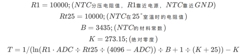
(The following is a quick lookup mapping table for frequently used 50°C-79°C temperatures and ADC return values.)
| Actual Temperature (°C) | Raw ADC | Actual Temperature (°C) | Raw ADC | Actual Temperature (°C) | Raw ADC |
|---|---|---|---|---|---|
| 50 | 1191 | 60 | 941 | 70 | 741 |
| 51 | 1164 | 61 | 918 | 71 | 723 |
| 52 | 1137 | 62 | 897 | 72 | 706 |
| 53 | 1110 | 63 | 876 | 73 | 689 |
| 54 | 1085 | 64 | 855 | 74 | 673 |
| 55 | 1059 | 65 | 835 | 75 | 657 |
| 56 | 1034 | 66 | 815 | 76 | 642 |
| 57 | 1010 | 67 | 796 | 77 | 627 |
| 58 | 986 | 68 | 777 | 78 | 612 |
| 59 | 963 | 69 | 759 | 79 | 598 |