Fashionstar Atom X: 17-DOF Biped Robot
1. Introduction
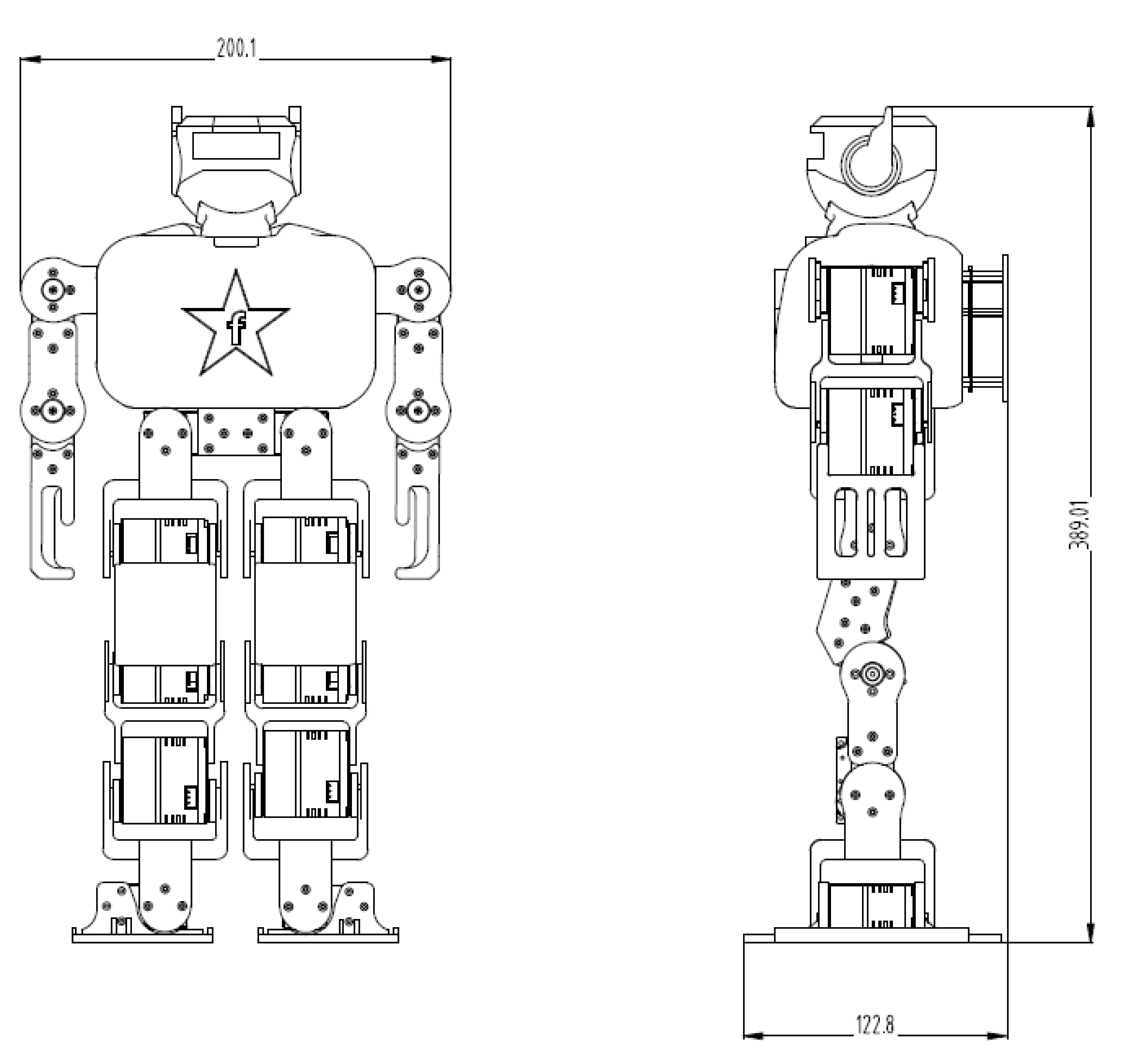
- Project Name: Fashionstar Atom X 17-DOF Open Source Robot Kit
- Overview: This is a fully open-source 17-DOF humanoid robot designed to provide robotics enthusiasts with a low-cost and highly playable hardware platform. Its core power comes from 17 Fashionstar RA8-U25H-M bus servo units. With a minimal electronic architecture, you can focus on motion algorithm development.
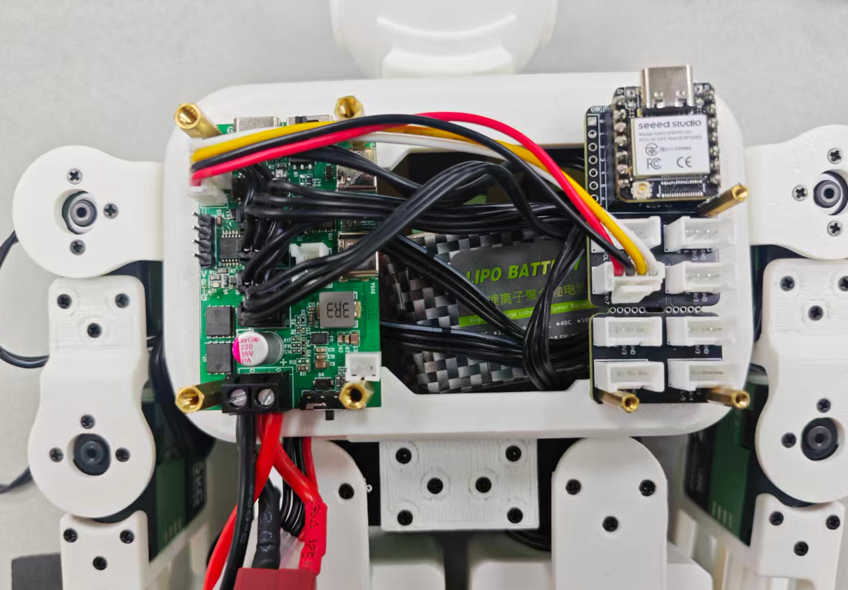
- Robot Architecture: bus servo + RUC-01 adapter board (power/communication) + Seeed Studio XIAO controller (optional Grove expansion) + 3D-printed structural parts.
- DOF Configuration: The whole robot has 17 DOF, covering the head, arms, and leg joints.

- Joint Actuators: Fashionstar RA8-U25H-M bus servo x 17 (supports bus communication for clean wiring).

- Robot Frame: Fully 3D-printed structure with STP/STL files available for download. Damaged parts can be reprinted at any time, and the appearance can be redesigned as needed.

- Control and Interfaces: USB Type-C (for PC configuration software access and configuration), UART serial port (host-controller communication), bus servo ports, and optional Grove expansion ports.
- Web Visual Action Editor: Provides an installation-free web control platform that supports real-time servo configuration and teaching-mode programming. Completed action group data can be exported as a standard
.jsonfile, making it easy for controllers such as Arduino, STM32, and Raspberry Pi to parse and integrate.
- Ready to Use: Compatible with the Seeed Studio XIAO series as the default controller and provided with a factory demo program.

- Multi-Module Expansion: Used with the Seeed Studio XIAO expansion board, the onboard Grove ports can connect to Seeed Grove sensor/controller modules.

- Cross-Platform Compatibility: To lower the development barrier, we provide the RUC-01 adapter board with onboard 5V/3.3V power output and a UART interface. Any controller with serial port capability can communicate with it.

Tip
Want to run Python AI? Connect a Raspberry Pi. Want IoT control? Connect an ESP32. Want to learn low-level control? Connect an STM32 or Arduino.


2. Hardware Architecture


2.1 Drive and Power Management (RUC-01 Interface Board)
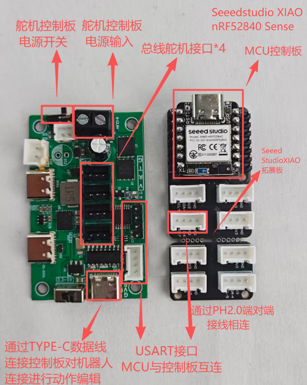
The drive and power management module (RUC-01 interface board) acts as the robot's power hub. It manages bus communication and power distribution:
- servo Communication: Four onboard bus servo ports (supporting daisy-chain expansion) provide signal and power for the 17 bus servo units.
- PC configuration Port: Integrated USB Type-C port for direct connection to the PC PC configuration software for action group editing and configuration.
- System Power: Handles voltage conversion and provides stable power input for the controller board.

- Communication Interface: Provides a standard UART serial port for receiving control commands from the upper-level controller board.
2.2 Logic Controller and Expansion (MCU + Grove Shield)
The logic controller and expansion module (MCU + Grove Shield) acts as the robot's brain. It runs control algorithms and processes sensor data:
- Core Controller: Uses a Seeed Studio XIAO series development board, which is compact and capable.
- Ecosystem Expansion: The Grove expansion board exposes rich general-purpose interfaces.
- Main Function: Runs robot kinematics programs and connects seamlessly to sensors through Grove ports, such as ultrasonic, vision, and voice modules, to support complex interactive functions.

2.3 Data Flow
configuration / Editor Mode (Debug Mode)
PC --(USB)--> RUC-01 --(总线)--> 舵机
Description: Adjust servo angles and save action group data directly through the computer software, without passing through the XIAO controller.

Autonomous Mode

传感器/遥控器 --(信号)--> XIAO --(UART 指令)--> RUC-01 --(总线)--> 舵机

Description: The XIAO controller autonomously controls robot actions based on sensor feedback or preloaded code.

3. Robot Structure
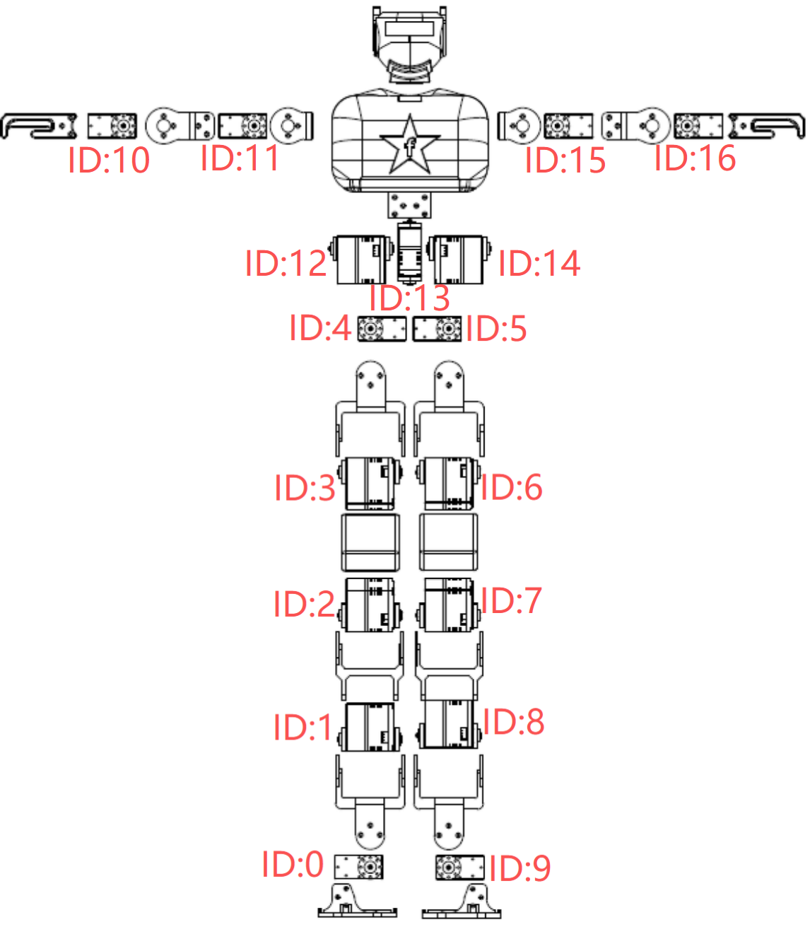
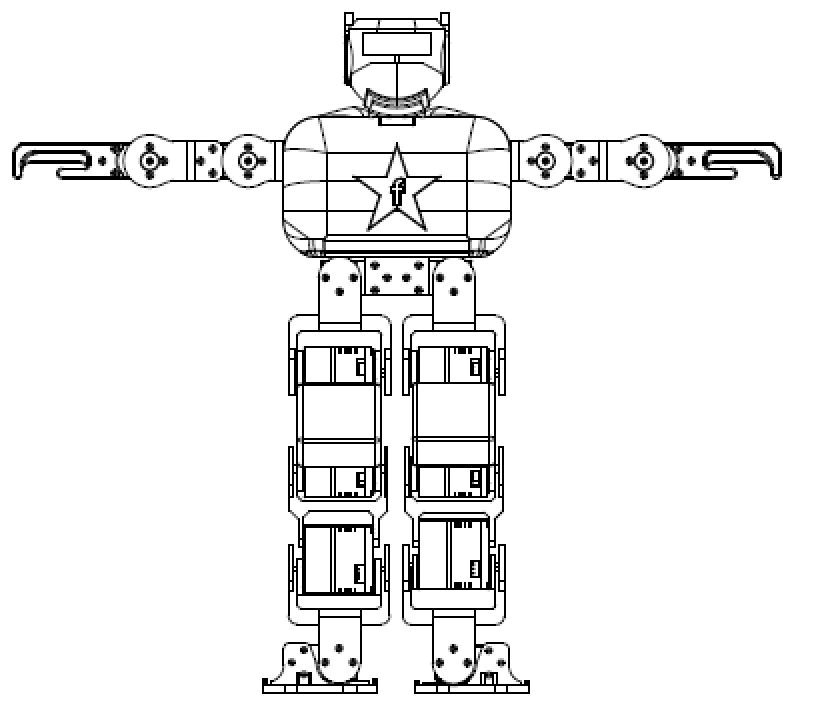
- Robot structure overview and default servo ID numbers
- Zero-degree posture when the robot servo units are at zero degrees

4. Action Editor Guide

Web Action Editor: https://wiki.fashionrobo.com/uartbasic/robotstudiopro/
4.1 Editor Layout
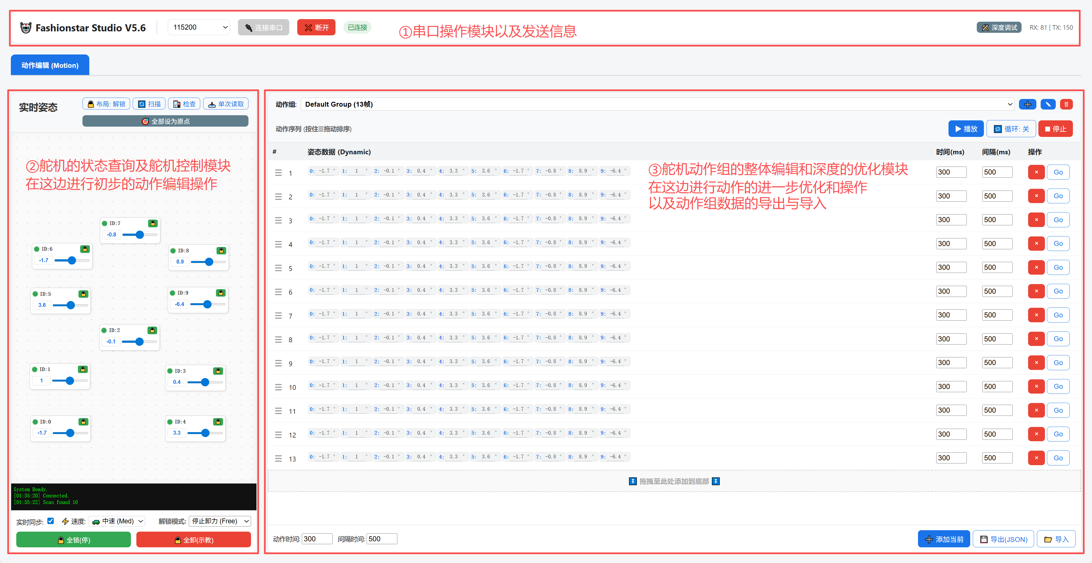
The action editor is divided into three modules:
- serial port connection/disconnection operations and message status module
- servo status/angle query and angle control module
- Robot action group optimization and action group data export/import module
4.2 Editor Controls
4.2.1 Serial Port Connection and Disconnection
4.2.2 Real-Time Posture Page
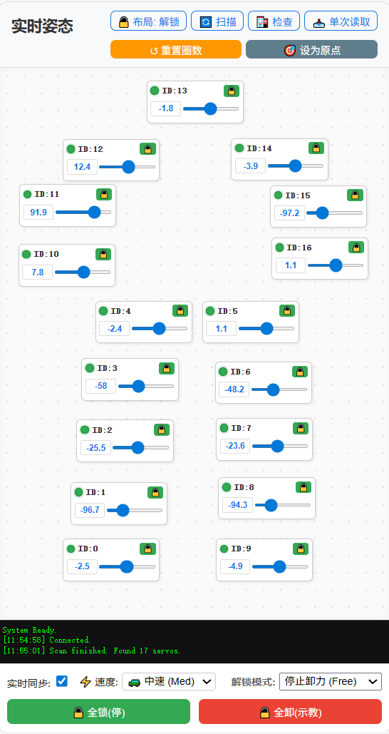
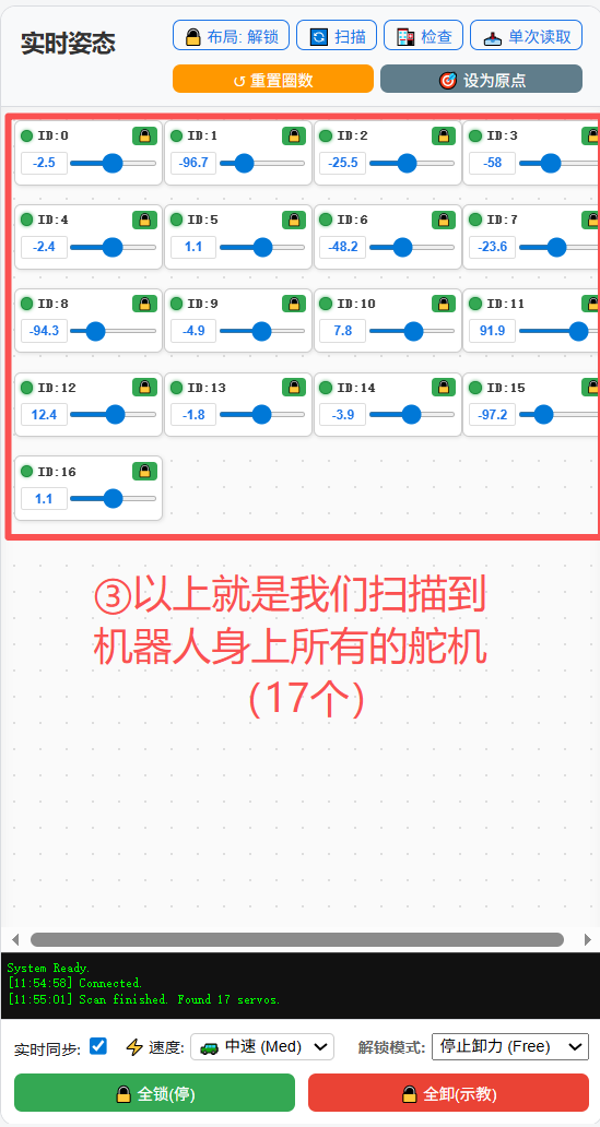
- Layout: Each servo control can be dragged on the canvas so that the robot's position can be arranged and matched with the corresponding ID number. Click to lock the layout.
- Scan: Re-scan all online servo units in the robot.
- Check: Click to check for abnormal states such as overvoltage/undervoltage protection and stall.
- Read Once: Read the real-time angle of the servo once.
- Status Colors: Green indicates that the servo is in angle control state. Red indicates that the servo is in torque release or damping release state.
You can control the servo angle by dragging:
- Real-Time Read: Read the angle of the servo in real time.
- Speed: This speed is the speed used by the upper drag slider for servo angle control, preventing servo angle control from moving too fast.
- Unlock Mode: Release the servo for easier action editing. Torque release and damping release are supported.
4.2.3 Action Group Data Page
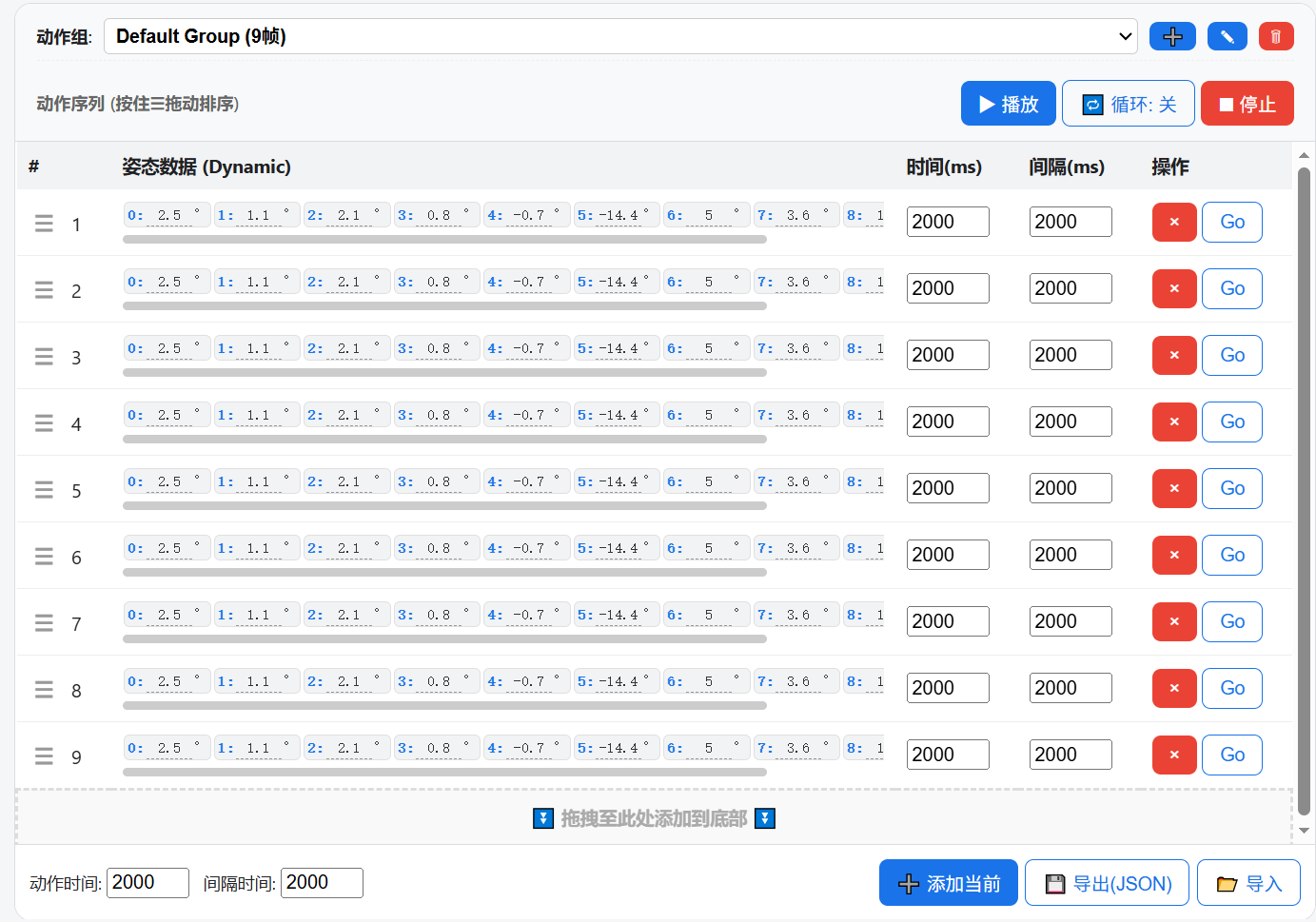
- action group: Users can configure action group items freely, with no quantity limit.
- Add Action Group
- Check Abnormal Status (overvoltage/undervoltage protection, stall, etc.)
- Delete Entire action group (keep at least one group)
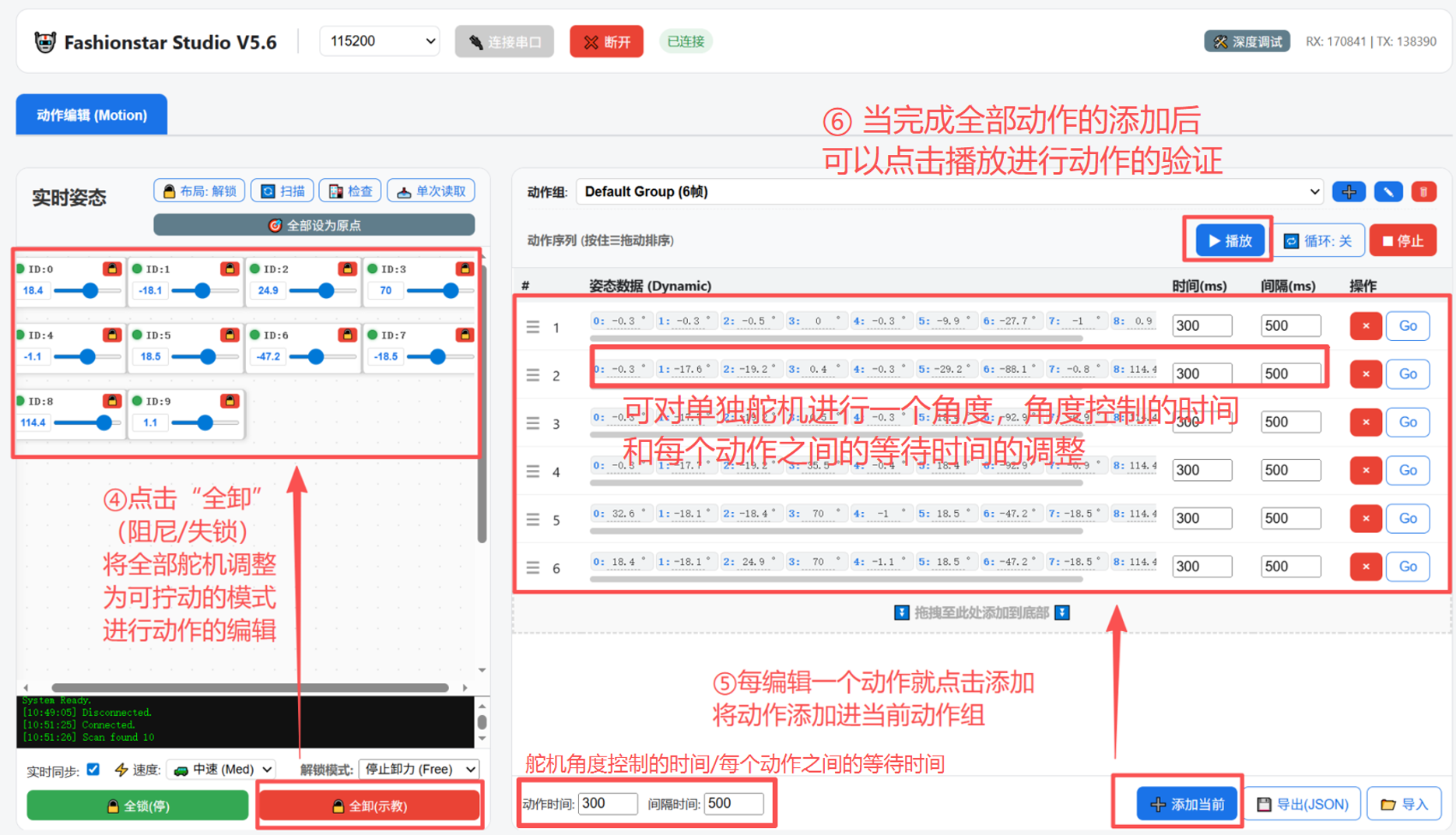
- Motion Verification: Click to verify all newly added actions.
- Loop Playback: Enable loop playback to repeat actions.
- Stop Playback: Stop playback of the action group.
- Adjust Action Order: Drag individual actions to change their order.
- Action Time (Time): The time required for the servo to move to the target angle (2 s in the example).
- Interval: Waiting time between actions.
- Delete Current Action
- Run Current Action
- Add Current Edited Action
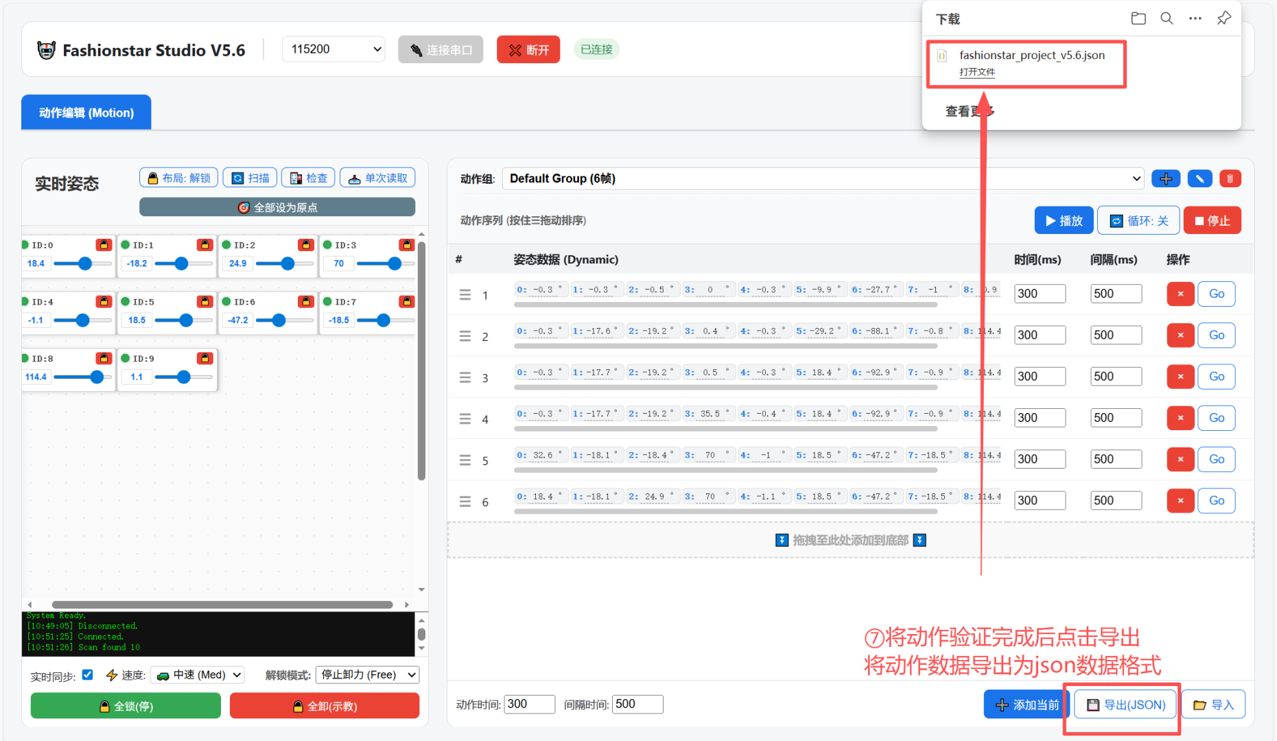
- Export action group Data: Export the servo data for the entire action group, making it easier to import into a controller.
- Import action group Data: Import existing action group data and modify it.
4.3 Workflow from Action Editing to Offline Robot Actions (Example: Seeed Studio XIAO ESP32S3 Sense)
- Click "Connect serial port" to establish a serial port connection with the robot.
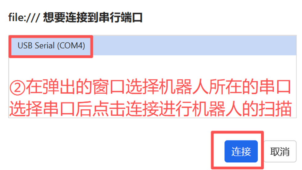
- Select the serial port where the robot is connected.
- Scan all servo units on the robot.
- Click "Release All" to release all servo units on the robot for manual posing. If you only need to edit the hand or leg servo units, unlock only the required servo units for action editing.
- Set "Action Time" and "Interval".
- After each action is edited, click "Add Current" to add the robot's current action to the current action group.
- After action group editing is complete, click Play to verify it.
Description: Each individual action can be edited and verified separately, including the angle, time, and interval of a single servo.
- Click "Export (JSON)" to export the action group data as a JSON file.
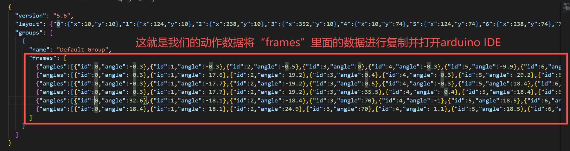
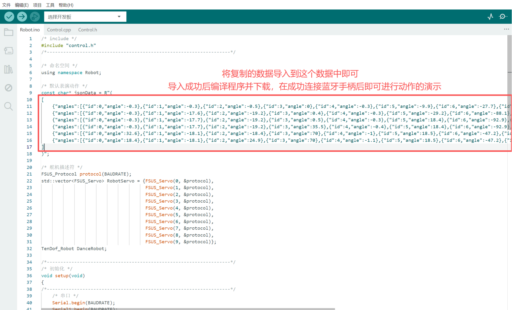
- Open the exported JSON file and copy the content inside
frames, including all content inside[]. - Replace all content inside
jsonDatawith the content copied from the JSON file. After that, compile and download the program to the control board, then control the robot with a Bluetooth gamepad. For details, refer to the "Robot Control Parameters" section.
5. Robot Control Parameters (Modify According to Actual Conditions)
5.1 Default Robot Parameters
BAUDRATE: Robot Serial Port baud rate.SERVO_NUM: Number of robot Servo units.
5.2 Bluetooth Parameters (If Used)
BLE_NAME: Bluetooth gamepad name.BLE_UUID: Bluetooth gamepad UUID.
5.3 Web Remote Parameters (If Used)
SERVICE_UUID: Service ID.CHARACTERSTIC_UUID: Characteristic ID.
5.4 Teaching Mode Parameters
MAX_ACTIONNUM: Maximum number of Action Group items in teaching mode.Default_RobotRunSpeed_Demonstration: Default running speed in teaching mode.MIN_RobotRunSpeed_Demonstration: Maximum running speed in teaching mode.MAX_RobotRunSpeed_Demonstration: Minimum running speed in teaching mode.Adjust_RobotRunSpeed_Step: Step value for adjusting the teaching-mode running speed, adding or subtracting 200 each time.
5.5 Data Description (Modify as Needed)
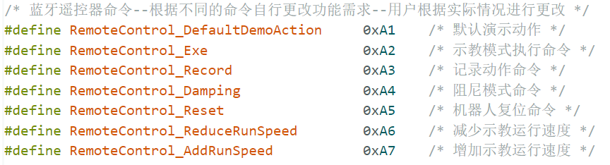
RemoteControl_DefaultDemoAction: Default demo action, that is, the action created by the user through the action editor.RemoteControl_Exe: Teaching-mode execute command.RemoteControl_Record: Teaching-mode action recording command.RemoteControl_Damping: Damping mode command.RemoteControl_Reset: Robot reset command.RemoteControl_ReduceRunSpeed: Decrease teaching running speed.RemoteControl_AddRunSpeed: Increase teaching running speed.
Bluetooth gamepad note: Users need to confirm the exact data from their own remote controller and determine their button requirements before modifying the control program.
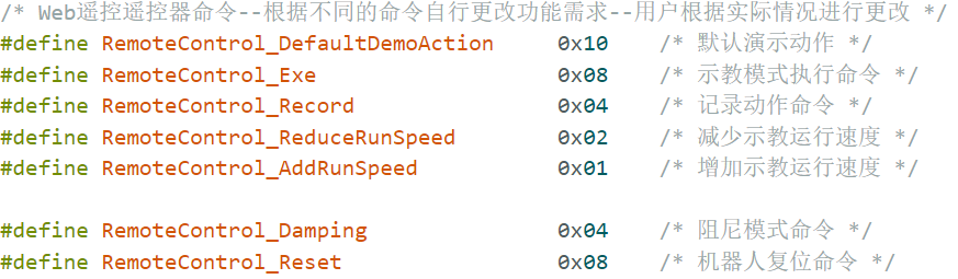
Web remote note: Users also need to confirm the exact data from their remote controller and determine their button requirements before modifying the control program.
5.6 Robot Reset Angle Parameters
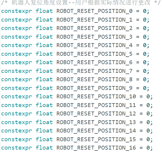
ROBOT_RESET_POSITION_0~ROBOT_RESET_POSITION_16: Zero-position angle settings for Servo ID 0 through Servo ID 16 (robot reset angles).
Description: Modify these parameters according to your robot's reset angles.
6. Remote Control
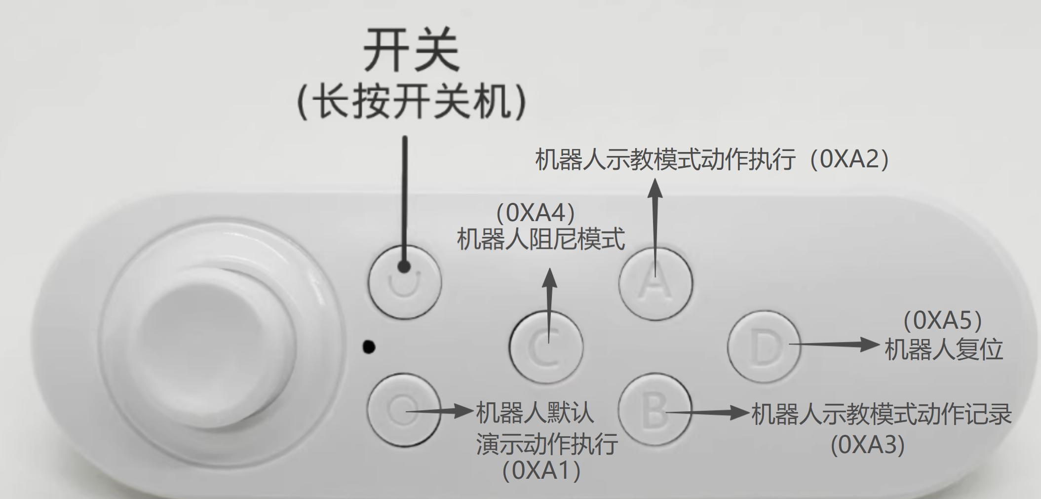
6.1 Bluetooth Gamepad Button Guide
- Long-press the Bluetooth gamepad to power it on and pair it with the MCU (XIAO_ESP32S3) over Bluetooth.
- After the Bluetooth gamepad and MCU are paired successfully, the robot performs a bowing action and resets.
Operation guide:
- Press "Run Robot Default Action": the robot runs a built-in action.
- Press "Robot Reset": the robot returns to the default reset action.
- Press "Robot Damping Mode": the robot enters a movable state, allowing users to edit teaching actions in damping mode.
- Press "Record Robot Teaching Action": the robot records the pose currently set by the user.
- Press "Execute Robot Teaching Mode Action": the robot executes the teaching action just recorded by the user. It is not cleared by default after execution.
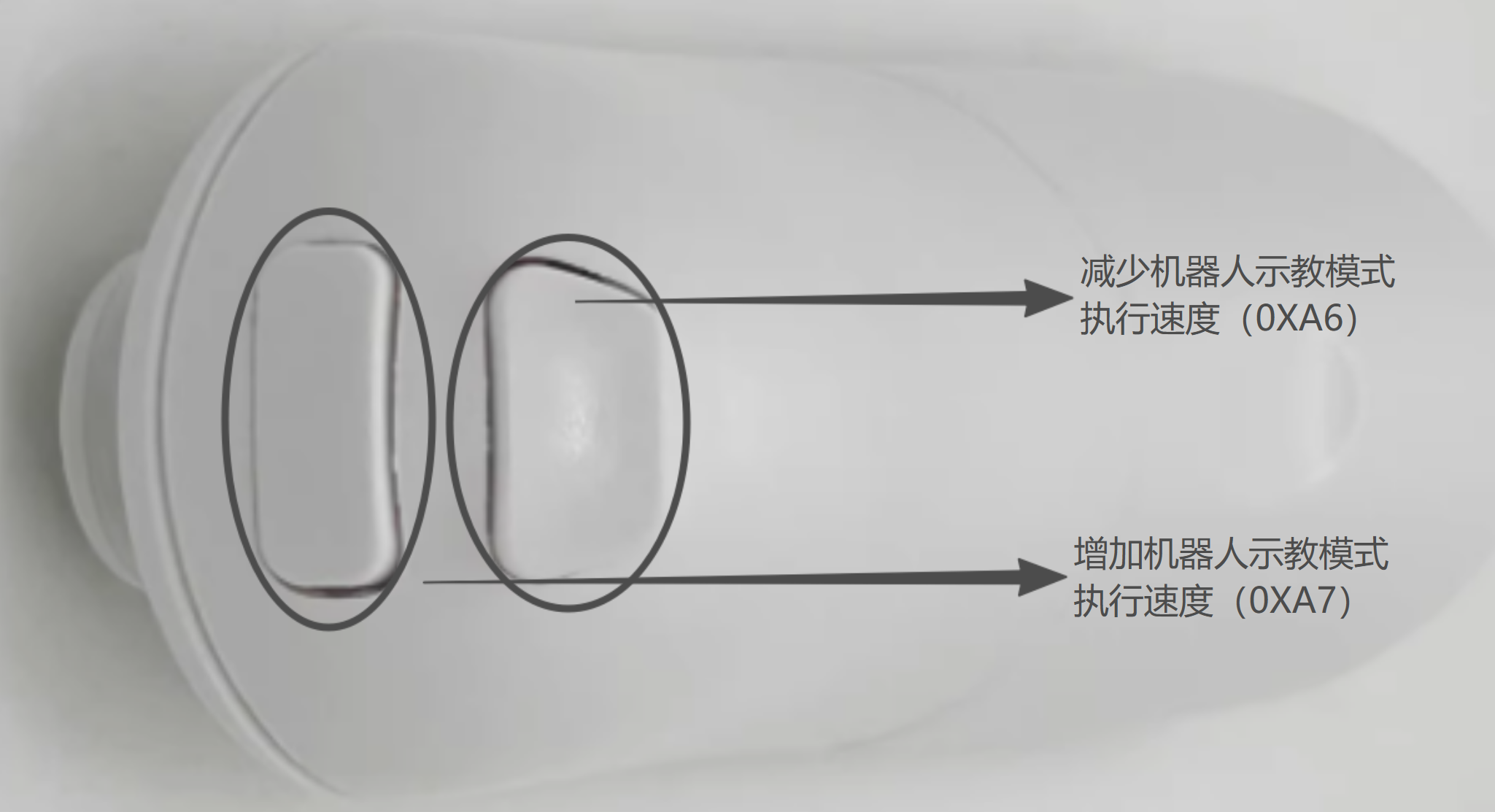
- Press "Decrease Robot Teaching Mode Execution Speed": the system decreases the running speed for the robot's teaching action. servo ID 13 in the robot head rotates left and right to show the current action speed.
- Press "Increase Robot Teaching Mode Execution Speed": the system increases the running speed for the robot's teaching action. servo ID 13 in the robot head rotates left and right to show the current action speed.
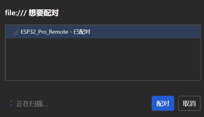
6.2 Phone/Computer Web Remote Guide
- Disconnected state.
- Search for the device and click Pair to connect.
- Connected state: after the web remote and MCU are paired successfully, the robot performs a bowing action and resets.
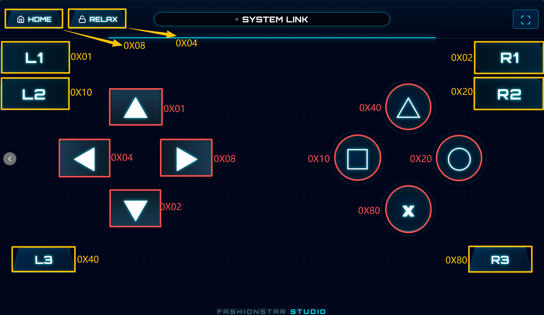
All web remote key descriptions: in the program, the "red" key data is stored in btn_Main, and the "yellow" key data is stored in btn_border.
In the demo program, the default remote key definitions are as follows:
- Red
0X01: "Increase Robot Teaching Mode Execution Speed"; the system increases the running speed for the robot's teaching action. Servo ID 13 in the robot head rotates left and right to show the current action speed.0X02: "Increase Robot Teaching Mode Execution Speed"; the system decreases the running speed for the robot's teaching action. Servo ID 13 in the robot head rotates left and right to show the current action speed.0X04: "Record Robot Teaching Action"; the robot records the pose currently set by the user.0X08: "Execute Robot Teaching Mode Action"; the robot executes the teaching action just recorded by the user. It is not cleared by default after execution.0X10: "Run Robot Default Action"; the robot runs a built-in action.0X20~0X80: undefined by default.- Yellow
0X01~0X02: undefined by default.0X04: "Robot Damping Mode"; the robot enters a movable state, and users can edit teaching actions in damping mode.0X08: "Robot Reset"; the robot returns to the default reset action.0X10~0X80: undefined by default.
Web remote link: https://wiki.fashionrobo.com/ps2v2/
7. Appendix
- Fashionstar servo Wiki documentation:
https://wiki.fashionrobo.com/ - Provides servo control SDKs for STM32 / Python / ROS / C++ / Arduino